First, thanks everyone for the advice on laying track. Things are moving along and I have about 80% of the track down and have wired one loop of the layout and ran some trains, old tycos and athearns from 50 years ago that my father had and some new Bachmanns and Walthers that I recently purchased.
I want to start wiring the layout into blocks and some questions arose that I would like to share with you all for advice please.
I’ll try to get to the point as succinctly as possible but if you need more information to offer guidance just let me know what you need and I’ll post right back.
I ordered the Atlas 215 selectors for the blocks but I am now noticing that there is a connection for each switch for only one wire. Does that insinuate that I would wire the layout with common rail and each block would get the second wire from the selector? If that is so, what I can’t visualize is how to dispurse the wire for the common rail from the powerpack to all the different blocks? I assume there is a device that takes one input from the power pack and then on the output side there are multiple termimals to send wires to the different blocks? Please forgive me if there are terminology gaffs. I feel like a 3rd grader trying to ask a question.
On another note I would welcome thoughts on gauge of wire to use. I scoured the forums looking for guidance and it seems for a DClayout 18 to 20 gauge is sufficient. I have Larry Pucketts’s book on wiring and he suggests 12 to 14 gauge for DC but that seems like overkill. Or maybe not? My layout is about 18 feet long and about 4 feet wide on the ends and narrow in the middle - dog bone shaped.
Thanks! I would be happy to post my layout as grist for the mill if you are interested.
This is a valuable addition to any model railroaders library- -whether using DC or DCC.
It not only describes the application of the Atlas components but also gives schematics for the more technically inclined.
Unfortunately, it is currently listed as Backorder on the Atlas website.
To answer your question about the Atlas block switches- -yes, they do use a common ground that is NOT gapped on the “negative” rail for DC use.
A single wire from the “negative” side(s) of the cab(s) can be daisy-chained from one cab to the next then to the track or distribution unit.
If you are concerned about voltage drop on the “negative” common rail you have a couple of options:
You can use a single bus wire for the “negative” common and attach feeders to the track at set intervals, similar to a DCC bus but only for the “negative” side of the cab(s).
Another option would be to use terminal strips (A.K.A. terminal blocks or barrier strips). These come in “sizes” from 2- to 10-terminals.
To energize the entire strip you can fabricate jumpers from spade connectors and short pieces of wire or buy jumpers made of solid metal to connect the terminals.
From there it’s a matter of running wires from the lugs (screw terminals) on the terminal strip to the track section.
Before converting my 4’ X 8’ pike to DCC I had 16 control blocks (4 atlas controllers) with only a single “negative” common.
My layout is 14’ x 10’ and the mainline is a twice around. I have 14 blocks on the mainline. I do not use common rail. Each block is a homerun to my control panel using #19 solid bell wire. Each block is controlled with a DPDT center off toggle switch. My longest block run is about 16 feet. #19 solid wire has 1.8 amp capacity, that’s 1.8 amps to each block. Two locomotives draw less than 1.8 amps working together.
I designed and built it before DCC. In 2006 I went with DCC but I added a relay to switch the track power from my DC power pack to my new DCC controller. I operate my layout dual mode, DC or DCC.
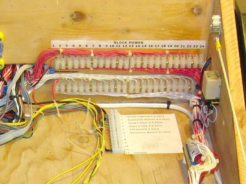
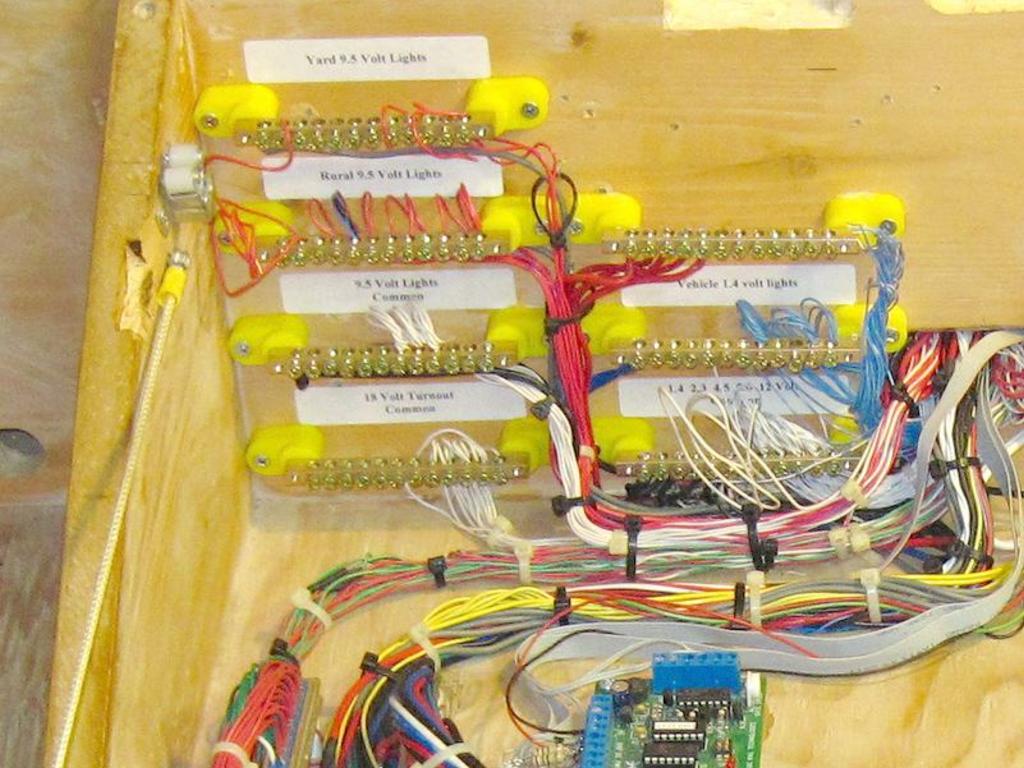
I use EURO Terminal Strips for my block wiring and Busbars for power distribution.
Mel
Modeling the early to mid 1950s SP in HO scale since 1951
Atlas uses common rail (it doesn’t matter which “pole” is used as a common rail just btw) but there’s no magic to that.
The only way common rail is different to standard DC or DCC two wire bus wiring is common rail relies on the rail only to feed current to one side of the circuit. Like a train set oval.
That’s the drawback. Any fair sized layout benefits from using multiple feeders to each rail for reliability.
I recommend you ignore the common rail aspect (although all DC layouts are essentially common rail no matter what people say about how theirs isn’t) and wire all your blocks with double isolators, each block will be a separate “layout” electrically. That way if you ever decide to convert to DCC or get a dual mode power supply like MRC Tech 6 you’re all set. Troubleshooting a divided into separate blocks with power fed to each rail is much easier than with true common rail where a failure of the common rail side can crash your whole layout and you have no idea where to start troubleshooting. For DCC not using common rail is a good idea for the same reason. In its simplest form DCC uses common rail for each rail. That’s one big advantage of DCC, until it crashes.
To achieve this you run a power wire from one powerpack terminal under all of the tracks. I run the red wire as the “common wire”. This duplicates the common rail side of Atlas wiring diagrams so you can use all their switch gear easily. Then you drop rail feeders for the “common rail” to power one rail in each block.
The other “rail” in each block is fed from the Black wire attached to the other pole of your powerpack but that wire runs through your 215 selectors. But this “bus” wire only runs to the input side of your 215 Selector switch(es). Then you run separate black wires from each 215 Output terminal to the desired blocks. The main wire from you
I have a DC layout as well. (Don’t intend to go DCC. Too many engines = too much expense.) I have 24 power blocks on it. (Reverse G shape 24’ x 12’ approx Rail yard area) As already stated if you’re only using one power pack Atlas Connectors (yellow switch) are good enough (8 of them on my layout). Another thing that I have done on my layout is with my remote turnouts. On my Atlas twin coils each turnout has its own set of outer wires (Yellow and blue for me) but the green (control) is daisy chained from the control panel to each of them. (Less wire use and works just fine.) But how you do it is completely up to you. It is your layout.
Like any wiring or control system, common rail has it’s advantages and disadvantages. It’s been around for decades, so if that isn’t indication that it works fine I don’t know what is. On a layout your size, it would be a good idea to fully insulate sections of it that can easily be disconnected from the remainder of the system should the need ever arise, but otherwise, carry on with your plan of using the Atlas selectors. They will work fine for you.
I ran a layout for years using two Atlas 220’s hooked up exactly as their diagrams indicate and it worked flawlessly. Curious what you’ve run into.
I found that the positive and negative input connectors are not as illustrated. The “inner” terminals are the same polarity and the outer terminals are the same polarity. Atlas implies the opposite in their diagrams. The polarity also doesn’t run “straight through” as you might expect. Older 220 with four outputs as well as four inputs reveal this oddity. Later design do not carry the “ground” polarity across the unit, Atlas no doubt realized that wiring the ground to the last 220 in a chain was all that was required actually so deleted the ground connectors, which were the outer pair of terminals at the input and the inner pair at the output.
Looking at the schematic wiring diagram for the 220 confirms what I discovered myself by trial and error, after a frustrating afternoon of my layout not working. I also discovered the faulty brand new 220 units in similar fashion,
That may be so for block control to run more than one train at a time.
My common rail DC layout, not counting staging yards, industrial sidings and areas of double track, has roughly 300’ of mainline, all of it powered through these two wires…
Power is from an MRC Controlmaster 20, running through a Stapleton PWM walkaround throttle. I’ve run over a dozen locos at a time, without issues or slowdowns. I use double throw/centre-off toggle switches to control the double-tracked areas and simple on/off toggles to control the individual tracks in staging yards and some industrial tracks. Couldn’t be simpler.
Several hard-to-reach turnouts are are powered by wall warts (1 Tortoise, 4 Rapido motor drives, and 2 PFM/Fulgurex rack drives.
Maybe I would have to see it, but I’m not following the issues you are bringing up. Did you wire them from right to left? Maybe using the “wrong” directional switches? Seems odd that something that was manufactured right would all of a sudden be manufactured wrong and keep being manufactured wrong. Not saying you didn’t experience issues, but maybe there is something at play that was missed.
As for quality, I know people dog on Atlas’s #56 switch controllers, but I’ve not had a failure with them personally, even using numerous ones for years, so I won’t say they are poor quality. I’ve also used numerou
Common rail works fine and it has worked fine since the beginning of model railroading. Personally I’ve always liked the ability to reverse direction in individual blocks and that requires both rails switched in a DC operation.
All my layouts from 1951 to 2006 were DC only and I’ve always switched both rails. I also like the ability to just turn off the power to both rails to individual blocks.
When I went DCC in 2006 I tried the DCC Guru way (buss wiring) and didn’t like it. The buss wiring screwed up my very nice signaling system so I went back to DC Block wiring for my DCC system. Every thing works great, DCC isn’t rocket science and the data rate at 8.5kb will work fine on even the worst wiring out there. All you need is the current carrying capacity to handle your load. An HO locomotive uses about 600ma to 700ma under full load, figure out how many locomotives you will operate in a single block and size your wire for that amount of current. In my case I never run more than two powered locomotives per train so I sized my wiring for a 2 amp max load per block. I went with #19AWG solid bell wire from my local Big Box store, twisted red and white low cost wire. I haven’t had any problems with my wiring for over 33 years.
I operate my layout dual mode, DC or DCC, never both at the same time. To simplify the switching from DC to DCC and back I use a DPDT relay to switch the rail power between the two power supplies. I use the Accessory voltage from my DC power supply to operate the relay coil so that when I turn on the DC power supply the relay pulls in and switches the rail power from the DCC controller to the DC power supply, fail safe and no memory cells needed. I’m almost 84 and my memory cells aren’t what they used to be.
Mel
Modeling the early to mid 1950s SP in HO scale since 1951
Lastspikemike
I found that the positive and negative input connectors are not as illustrated. The “inner” terminals are the same polarity and the outer terminals are the same polarity. Atlas implies the opposite in their diagrams. The polarity also doesn’t run “straight through” as you might expect. Older 220 with four outputs as well as four inputs reveal this oddity. Later design do not carry the “ground” polarity across the unit, Atlas no doubt realized that wiring the ground to the last 220 in a chain was all that was required actually so deleted the ground connectors, which were the outer pair of terminals at the input and the inner pair at the output. Looking at the schematic wiring diagram for the 220 confirms what I discovered myself by trial and error, after a frustrating afternoon of my layout not working. I also discovered the faulty brand new 220 units in similar fashion, tracking the internal wiring faults using a multi meter and the schematic if what was supposed to be connected and disconnected by the various sliders. Clever design, poor manufacture. A major deficiency of all Atlas switch units is the center off slider switches. The red polarity reversing switches in particular are very poor quality. The blue turnout motor switches are a close second.
Maybe I would have to see it, but I’m not following the issues you are bringing up. Did you wire them from right to left? Maybe using the “wrong” directional switches? Seems odd that something that was manufactured right would all of a sudden be manufactured wrong and keep being manufactured wrong. Not saying you didn’t experience issues, but maybe there is something at play that was missed.
I wouldn’t think it should matter DC or DCC. Power attenuates over longer distance. So it depends on how long your bus is. There are tables you can google for DCC, for example, that would be also good for DC.
Tables I’ve looked at indicate that runs of less than 50’ you can use 14 AWG wire for your bus. Longer than that and 12 AWG. I purchase rolls of 14 AWG house wire from Lowes for my bus and am sticking with that for size and bus length.
I am am running staging track feeders at around 8 feet so using 20 AGW bell wire for those from Lowes.
No, the way common rail is different is one rail is electrically common throughout the layout (except for reversing sections if the layout has any). Most larger common rail layouts use multiple feeders for the common rail instead of relying on just the rail for feeding current to the common side of the circuit - they are still “common rail” layouts because they still use an electrically common rail.
I don’t know how you came about this idea but it’s simply not true.
You’re half right, if it will work for DCC it will work for DC, but the opposite is not necessarily true. Heavier gauge wiring is recommended for DCC for multiple reasons - the main ones being heavier loads (multiple trains running from single power supply) and detecting short circuits.
I look at the wiring and the tracks. It’s correct. Your perspective may disguise the reality. Layout wiring is pretty simple stuff. Red wire to one rail, black wire to the other rail.
In fact, one huge advantage of DCC is you can just hook up two wires to one connection track and your whole layout will be powered for multiple locomotive operation. Two common rails. No bus wires at all.
Adding bus wires and feeders doesn’t make it not common rail wiring. Cutting power to only one rail is what makes a system “common rail” straight toy speaking. For DCC you don’t need a “control rail”, Bith rails are common rails.
I think maybe you’re confused about what common rail wiring is. Take a DC layout with two blocks (to really be useful you need more than two bloacks, but this is just for demonstration), two cabs, and two trains running - block 1 switched to cab 1 and block 2 switched to cab 2. With normal (not common rail) wiring, you have cab 1 output A wired to block 1 rail A, cab 1 output B wired to block 1 rail B, cab 2 output A wired to block 2 rail A, cab 2 output B wired to block 2 rail B. Within each block you may have one feeder wire per rail or you may have a dozen, it doesn’t matter. You have two isolated circuits - there is nothinig common between them - there is no way this could be described as a common rail layout.
Now, if you wire cab 1 output A and cab 2 output A together and remove all of the isolating gaps between the blocks in rail A, but leave them in rail B, you have a common rail layout. It doesn’t matter if you have one feeder or 100 for the common rail, it’s still common rail because that entire rail is common and tied back to the common outputs from the two (or more) power packs.
Common rail doesn’t work with reversing sections, but you can certainly have reversing sections on a common rail layout, you just have t
I’m not confused. The idea of common rail confuses people because it seems to involve some of the things you describe. It doesn’t.
A toy train uses common rail power. A DC or DCC system with control rail gaps is common rail. Add just one reversing section and you no longer have a common rail system.
Too many people don’t understand common rail because of the way it is described. It’s just toy train wiring.
Things get a bit more complicated when you add a second power pack to a DC system in that you have to make sure you connect the red wires and the black wires correctly to the second powerpack (duh). You really don’t want to do that if you add a second power booster to a DCC layout. In fact, there are good reasons not to use full common rail wiring when building a DC layout but electrically your DC layout will still be common rail even if double isolated unless you also control your blocks with DPDT instead of SPDT which you forgot to mention.
It looks like you added this while I was replying. If you understand that double isolating the blocks breaks up the common rail wiring, then how do you come to the conclusion that " all DC layouts are essentially common rail."
Again not true, with common rail wiring you have full electrical conrol of the DC blocks.