First I model the mid to early 1950s in HO scale since 1951. My current layout was started in 1988 and far from finished, the Mel Construction crew are slow workers.
I’m just curious about the DCC wiring in newer locomotives. I haven’t bought a new locomotive in about 10 years and I’m wondering what changes have occurred and or the current way of wiring things.
I’m not into buying new locomotives for a couple of reasons, 1) retirement income, 2) I don’t plan on adding any new locomotives to my inventory, I have too many now. I just like to keep up on what’s going on.
I wired almost all of my 70+ older locomotives for a DCC decoder using the NMRA 8 pin connector many years ago. After buying a couple of newer decoders having the 9 pin JST connector I rewired several diesels for the 9 pin connector but left the 8 pin NMRA socket intact to accept a 8 pin DC dummy plug when the decoder has been removed so that they will operate on DC. I run my layout in both DC or DCC modes. About 30% DCC, when I’m working on or around my layout I let a DC train run my mainline loop at about a scale 35 MPH.
Early on I removed the 8 pin wiring and installed the JST connector in two E7 AB pairs. Later when I wanted to run them on DC I made a couple of JST DC dummy plugs.
I used an 8 pin socket for the connections to the E7 Model Power metal shell, my E7-A requires 6 wires between the shell and frame. 2 wires for the speaker and 4 for MARS and headlight.
I would like to keep my wiring as close to standard DCC as I can.
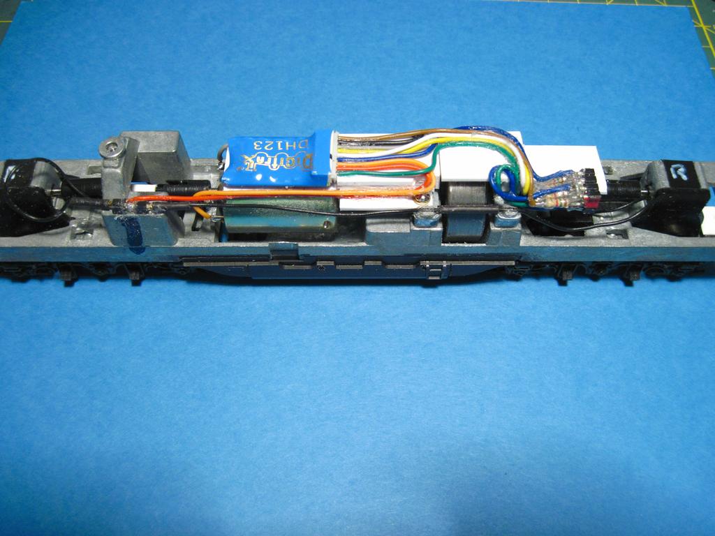
Way cool about swapping out different decoders. I was fearful of how to add the wires and found that the process is literally plug n’ play. The decoders you show are exactly what I have and they are on modern (read DCC ready) Athearn locos. I have one Bachman DCC ready loco and it should work that way. If not, coming here! [8o|]
A lot of engines made in the last 10 years or so have both the 8- and 9-pin receptacles, although in the last couple of years a lot of engines have a 21-pin receptacle instead of one of the others.
Besides what I would think is the hassle of having to open up an engine to take out a decoder and open up another one to add the decoder so I can run it on DCC, there’s the concern that everytime you do that you’re risking breaking one of pins on the decoder, rendering it inoperative. I’d suggest looking at just little by little adding decoders to all your engines. If you shop in bulk, like say 5 at a time, there are good non-sound decoders you can pick up for around $15 each (maybe less).
BTW, if you’ve removed a decoder from an engine, you do have to put in a dummy plug to run it on DC. However, the majority of decoders are ‘dual-mode’ so will work fine on DC without removing it.
Just remember, a dual mode decoder will not start running until the voltage is about seven volts DC. Nature of the beast. It does not need more power, just more voltage. The decoder wakes up at five volts DC.
Actually I’ve been swapping decoders and dummy plugs for close to ten years and so far I’ve never had a problem with breaking the connector pins. I use the round pin header strip connectors for all of my locomotives as well as for anything needing a small connector on my layout for at least 8 years and never a problem with the pins.
I have only used the JST decoder connectors for about three years and no problem there either.