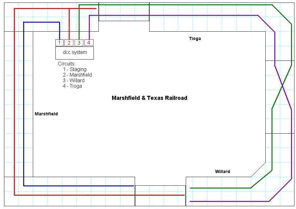
My benchwork is coming along nicely, soon to start laying some track. Here is the current version of my layout design - HO, 10x20 approx, twice-around with lower level staging, DCC, mostly solo or two-person ops.
Layout design:
Staging:
Now I’m starting to think about wiring. (Remember, I’m a nube - back in the hobby after a 25 year break.)
(EDIT: I originally used the term “DCC blocks” instead of power districts. I made this correction so as not to confuse everyone. Thanks, rrinker!)
I really could use your help with DCC power districts. From what I’ve read, my main purpose would be to break up the layout for troubleshooting the wiring and short isolation.
Originally I was thinking four power districts - 1 for each town and 1 for staging, protected by light bulbs.
Then I pondered an alternative - protect the whole layout with an actual circuit breaker and 4 SPDT switches to isolate problems.
What do you think - one approach better than the other? Also, any thoughts on 4 power districts - overkill or not enough?
There’s also something else that’s confusing me. I’ve read that some who run DCC still wire to deaden tracks (like tracks around a turntable) so that power isn’t going to “unused” locomotives. Got me wondering if each staging track should controlled with an on/off switch. Should I consider this?
I tend to over-analyze sometimes. So now I’m back to KISS. It’s mostly solo ops and the layout’s not that big, right? Protect it with one circuit b
4 blocks is probably plenty, if it’s only goign to be you and maybe one other operator. But use 4 breakers, not one. You can Also add the toggles to complete power off a section. If your staging is hidden, it might be a good idea to have some sort of arrangement to turn off all but the active track, to prevent accidents. Same with an engine facility.
If you plan to add occupency detection for signalling, you’ll need more than 4 blocks. Usually the DCC ‘blocks’ are called power districts to avoid confusing with signalling blocks. Each one fo the 4 power districts would be broken down into several detection sections. If you have plenty of track feeders this won’t be hard to go back and do later, you can cut the extra gaps for the detectors with a Dremel and if there are plenty of feeders already in place there won’t be any dead sections after you do that.
My layout is in a 9 by 23 foot room, around the walls, with an upper level that is 21 feet long. I divided up into 3 power districts. One for the upper level and then split the room down the center the long way for the other two, one on each side. I am also adding block detection and signals. I am using one Digitrax BDL-168 (16 blocks each) for each power district.
Hope this helps.
Not a bad plan, however considering how the staging area is designed I think I would use one for each end (however see design note below). Two reasons for this. 1 is the amount of power used by each section. With 4 tracks worst case is the potential of 4 powered ABBA type locos/w sound on the point of each. Second, is for problem isolation. This would isolate the problem to one side or the other. Especially true if this is hidden staging.
DCC units have circuit breakers built in. This solution solves the trouble shooting issue but not the short isolation. When they are all powered on one short would still shut down the entire layout.
Yes, That would eliminate the need for two power districts in the hidden yard. If the locos are powered off they are not taxing the power supply so one can get by with smaller power supplies on fewer districts.
I was wondering if the staging wouldn’t be better done in reverse of how you have it. That is have the ladders on either end and then
I may be reading it wrong because I’m not familiar with the area being modeled, but it seems liek he has the best of both worlds there, train finishes a run adn heads into an emptry track, to restage it just backs into the opposite side yard track and it’s ready to go out again. At least for through trains. Turns would require rearranging at least the loco and caboose. FLip the staging ladders and it woudl be easier for turns but not as convenient for through trains. Got any extra room to squeeze in a couple staging tracks both ways at each end?
The problem I see with putting the staging ladders on the opposite ends is then it would be on the grade, or else the visible trackage would have to be reduced.
Randy, you are correct. My operating scheme is mostly through freight. I explained it in a thread last fall where I got tons of help on my layout design.
Also correct. I really wanted to stay away from turnouts on the grade.
The only turn I wanted to model was an off-layout paper mill, with loaded pulpwood gondolas going out and empties coming back. I couldn’t see how double-ended staging would help with that. The only idea I have on this is two trains in staging, one with loads and the other with empties, to sort-of simulate a turn.
To be honest, I never really thought about a combination of the two.
Back to the circuit breaker topic… I have a follow-up question if you don’t mind. Where’s the best spot to locate the dcc base unit and 4 circuit breakers? I was thinking the upper left corner - one bus running left (counter-clockwise) for Marshfield, a second running left to a control panel for staging, one running right to the upper right corner town, the last running right also to the bottom right town. Not sure if this make sense. Any opinions?
My layout is 33ftby 28ft, and is three decks, with two major yards and 3 staging yards. My choice of using 4 districts was predicated on how many powered diesels (with and without sound) might occupy a district at a given time. If the district bogs down, then too much diesel, not enough district. Anyway, the top deck is basically one big town, 3 yards, and some mainline to another town where it splits between holding yard and a helix downto middle deck. I have a booster on the major yard, one on the rest of the top deck. Second deck has one major town, small towns, and is a branch line type main. Not as many trains, it rates a booster of its own. Bottom deck has a major staging yard, a couple of minor staging yards, and mostly mainline track. It too has its own booster. That counts up to a total of 4 power districts, 4 boosters, using NCE, 12 gauge power buss and I never have any problems.
Regardless of where you put the power supply and breakers, you’re going to have a bus run of about 34 feet in each direction. I’d probably use #12 wire with that, certainly not less than #14. I would locate the power source closest to the busiest part of the layout, that way the part with the most current load will have the shortest length of bus wire to traverse. Hopefully that coincides with the furthest ditance being one of the lower traffc areas - voltage drop in the bus wire is related to the current drawn, so a 1 amp load at the 34 foot mark might be an unnoticeably drop but 5 amps at the same point might be.
Thanks Randy and Bob for your responses. Sorry it’s taken me so long to get back to this discussion. I do have a few more follow-up questions if you don’t mind.
First question relates to terminology. If I have the one power station and four circuit breakers, do I really have one power district and four “sub-districts”, or what are these four sections called?
I will go with the power supply on the left side which is the busiest part of the layout. I will also go with 12 gauge wire as you suggest. Now I have a question on the feeders. With a 24" wide layout and the bus wire running down the center, I could have some feeder wires of 12" or even a little longer. I’ve read that 20 gauge feeders is a common recommendation, so that’s my current plan. Is this going to be a problem in general accross the layout, or a problem in particular at the end of the 34’ bus run to the opposite corner of the layout?
Last question (for now at least) - For soldered wire connections under the layout, is it common/acceptable practice to leave them exposed? I was assuming I would need to wrap all connections with electrical tape or some other insulating material, but I’ve seen a lot of examples on the Internet to the contrary. Any advice on this?
Thanks in advance for your continued guidance. (If it weren’t for DCC and this forum, I never would’ve restarted this hobby after a 25 year hiatus.)
Yes, technically speaking the sections powered via a breaker from the same booster are sub districts since they don’t have their own dedicated power supply. You see it both ways though, no one has thus far laid down a law and said “it will be so”
#20 for feeders should be fine as long as you run enough of them - as in, to each stick of track, so thereis no relying on rail joiners to power part of the track. The end result will be so many #20 wires in parallel that it’s effectively heavier than the #12. And just see Cuda Ken’s section on his MRC booster for why the #12 or #14 wire is recommended for longer runs - he had #18 and it prevented his booster from tripping on a short.
I made a project of painting my soldered connections with liquid electrical tape. I didn’t do it right away, I ran for a while with bare soldered conenctions. But I also staggered them, so it was nearly impossible for two of them to touch and short out.
Hey, I’m back! Sketched some things out and thought I had a plan. Now I think I’m whacked again on this electrical stuff. Sure could use some more advice from Randy or anyone else willing to help.
My plan is to wire in support of four circuit breakers, but not actually buy them until my layout progresses and loco fleet is developed (which could be a few years). So I would start with just barrier strips, then maybe some toggle switches.
Here is a sketch of how I was thinking of running the busses (12 gauge) for the four districts.
For the staging, I would have toggles to only power one track at a time.
Does this make sense or is there a better way to do this?
I am building a layout not too different from yours (HO, 11x15, lower level staging) and have a Digitrax Super Chief with a second booster. Each of the two boosters is connected to a DCC Specialties PS4 circuit breaker set, yielding a grand total of 8 power districts.
I did a lot of research/questioning about the power districts, and ended up with the following split - based upon projected power need of course:
1.- incline from main level to lower level staging tracks. 2. - two lower level passenger staging tracks. 3. - four lower level freight staging tracks.
main level outer mainline. 5. - main level inner main line. 6. “sub-mainline” plus sidings/yard. 7.- Steam loco terminal tracks. 8. - Diesel loco terminal trackage.
The above should work out fine, but its always possible I may need to adjust or add another district. As I am now wiring the lower level, it has become very obvious that good records need to be kept, as well as keeping the wires marked (color coding helps a lot).
What I did so that I could add a breaker later was to rie in a heavy-duty terminal strip (found at Home Depot) and put jumpers from the input to the 4 outputs. I used wires, but it’s far easier to use the jumper bars meant for these things (although that means 2 strips, one for Rail A and one for Rail B). The overall plan was for the booster to power the input pair of terminals, which would connect to the breaker input. Each breaker output would go to a seperate pair of terminals to which each individual bus line would attach. By jumpering the ‘breaker’ side I merely connected allt eh terminals together. Remove jumpers, insert breaker, done.
I’ve used a similar approach with the heavy duty European barrier blocks from Radio Shack. Now I have all 10 blocks so the only junpers that are in place are where I still feed two bus segments from one breaker.
I’ve also got screw type connectors to use for most all of my power districts. As you wrote, this will allow me to easily split them up if the need for “more power” arises. I suspect my power district that will include the sub-main and all attached industrial sidings and the yard may be a prime candidate. But, as there will typically only be one operator, maybe all will be fine as is afterall.
Your (and my) point is that it is much easier to wire for expansion & changes during construction, rather than after the layout is up and running (been there, done that).
OK, now this newbie is confused again with this DCC/electrical stuff. I’m not even sure how to pose the question but I think it has to do with “sizing” the system.
With the size of my layout, eventually I would have a dozen or more engines sitting on the layout - seven staged trains and a few engines in the Marshfield yard. However, I’m only planning to support two operators. This means at any given time, I would have 2-5 engines (a triple and a double) running and the rest “unused”.
To size my layout, I am looking at amps - correct? If so, is it the engines in use or all the engines on the track?
More specifically - I purchased the MRC Advance 2 (I know some on this forum will cringe, but it seemed like the best fit for me - time will tell), still in the box but I believe it’s rated at 3 amps. Given this, do I need toggles to power off unused staging tracks, or do I need power booster(s), or am I good to go?
Again, I appreciate your patience, and your willingness to share your knowledge and experience.
I am wiring in toggles for my staging tracks (1 for the 2 passenger trks, 1 for the 4 freight trks), and also the loco terminal trks (1 for the 2 diesel loco trks, 1 for the 2 steam loco trks). My reasoning is that the locos do take up some power just sitting there (esp. if they have sound), and that power could be needed elsewhere. With you having a 3 amp system, I suspect it makes even more sense for you to do so. Also, I am toggling both wires going to the tracks. Yes, toggling only one should be ok, but I am doing both.
OK, after a bunch more Internet reading on this last night, this is where I’m at.
Originally, I was calculating total amps required for my layout as 6 engines max times .25 amps per engine, giving 1.5 amp, then double that. So a 3 amp system would be suitable. Idle engines sitting on the track - neglible so they don’t count.
But, they need for toggles is really a work-around for insufficient power - amps.
Not sure how to calculate, but I really need more than 3 amps - probably closer to 6 amps?
So, lose the 8 toggles and all that extra wiring for the staging, going back to one bus feeding all of staging. Instead, add more power (grunt here)! The “proper” DCC approach woudl be two power districts - one for staging, one for the upper level - and divide the upper layout into three sub-districts for circuit protection/troubleshooting.
Am I on the right track here, or still way out in left field?
I too had the same concerns for “more power”, originally wanting to go with a 5 amp system and 3 additional boosters. The knowledgable folks on this and the Yahoo Digitrax forums convinced me that I was going way overboard, and that a 5 amp Super Chief with a second booster would be more than enough - especially split into 8 sub-districts via two Psx4 circuit breaker sets.
I am a lone wolf operator (almost always) and typically would run two 4 unit ABBA consists (all powered) and perhaps a switching unit with my free hand.
Having read a lot about the subject (but with little practical experience), I would split your layout into a number of power districts and perhaps add a booster. Or, you may want to replace the Zephyr with a SuperChief later on - but I would sure go with what you have first to assure it is necessary. By the way, Digitrax systems have excellent resale value on Ebay.
Keep us informed, for your “problem” is probably shared by a number of folks.