I’m not a structural engineer, but I play one around here.
Of your options, the 36"/36" is the theoretical best. It will load the diagonal member least, and have the greatest effect on the leg movement.
As those numbers decrease, the utility lessens. Happily, not by much until you get way up close to the “joint”. I would say 12" is “way up close”, and 24" is not.
Great question. We overbuild everything so the “best” to minimize sway, may be more than you need unless you are dancing on top the layout. It’s a layout not a truss bridge.
Ed is right on the money. But remember, the longer the diagonal, the greater the restriction to under-table access. There are going to be some trade-offs in that regard. And the 36 inchers across the 48" ends will have to cross each other. But if any cross each other, bolt or screw them together for added stability.
Go to the top of page where the black bar is and click on ‘‘Get Started’’ once the topic’s show up…scroll down to the second one, which will be…‘‘Build a table for a small model railroad’’. They will show You how to build a 4x8 that You can either build it that way or gleam some ideas for Your own version…
A 12" x 12" triangle would do a nice job of anchoring rotation at the joint. But the legs below that 12" can still bend.
Consider that you can probably adequately lock up the joint (where the leg attaches to the layout frame) with TWO bolts/screws through the leg. Without the 12" x 12" triangle. This will, of course, do nothing about stopping leg bending and consequent sway.
I think in addition to lateral sway, which is prevented by any type of gusset really, you also want to minimize bending of the leg.
I’m going to struggle to explain this: Putting the support at the distance that will make the leg have the “shortest” unsupported distance will keep the leg from bending. That would be the middle.
So, for a 36 inch leg, my answer to your question is “none of the above”.
I would say 18 inches. The point at which the leg is bisected.
The stoutness of your diagonal support matters too. A thin furring strip could itself bend if it was too long, like it would be if you attached it to the bottom of the leg. If the supporting diagonal piece is thin, I would think attaching higher up the leg would be better since it would be less apt itself to bend.
We don’t have any popcorn either, but I can see the entertainment value potential of this thread. So, I’m sitting out and getting another slice of banana nut bread and cuppa coffee. And as for the walnut foo-foo business . . . around here nut bread is made with pecans. Thanksgiving is about the only time I get to have dessert after breakfast.
Yes, it could and would vibrate. If plucked. How often does that happen? That event will be much rarer than people leaning on or touching the layout edge.
But, even if it vibrates, I doubt that will be much of a problem. I just struck the middle of a leg (2x2 wood) on my layout. It made a thunky noise and not much else.
Wood legs are going to also be very self-damping in vibration.
I recall following many of the techniques in the Virginian project article (MR articles early 2012) for my 5’x10’ layout. Mine is similar in having overhanging ends. You might check out the related article for the layout framing, but the technique is also described in this one (Part 3) of the many Virginian project videos:
ANyway, it includes legs made of two 1x lumber pieces (1x4 and 1x3, I think) at 90-degree angles. It was easy to do that with some glue and a finish nailer. A 2x2 block near the bottom provides a place to mount rollers. I made my top frame, including joists, with 1x4 lumber. For my lower 1x4 horizontal stabilizer pieces I placed the back and side ones pretty low, maybe 12" above the floor, and the front one fairlly high (maybe 15" below the top) as a compromise, for easier access from underneath.
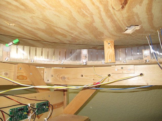
To your point, I added 1x3(?) diagonals, two at each spot where the inset legs join the top frame. I’d say about 18" down, which does not much restrict access. Those really stiffened things up. The following photo shows a diagonal, behind a 1x4 joist in the way of your view.
BTW, I assembled the 1x4 top frame on the floor, oriented so I was looking down on it so it resembled my diagram. I determined that it is a good idea to flip it over before adding the legs, unless you want the legs pointing up. I’m just concerned that someone might make that stupid mistake![:$] And, I can also advise how not to trim your door length to allow for carpet clearance!
If you’re building a 4 x 8 layout, and you just don’t want ANY angle braces on the legs, I suggest using 2" x 1/8" steel angle iron. The weakest point will be where you attach the top of the leg to the layout. I would recommend, for each connection, four bolts in the 3/8" diameter range arrayed in the obvious way.
Cost will likely be $50 or so, including the hardware.
I’ve used that technique before, and will use it a lot on my next layout. Its easier to take the twist or warp out of a 1x by mating it with another at 90 degrees. One board provides rigidity to the other. The result will tend to be straighter than a stock 2x board, IMO. It’s nearly impossible to take a warp or twist out of 2x with conventional hand/power tools.
I’ll work with 8 ft length boards and cut them to whatever shorter length I need. Just need to remember to mark where the finish nails are located before sawing.
I think it would provide a sturdier, straighter leg than 2x2s and even 2x4s, and provide a wider surface with which to screw angle boards or gussets into.
Oh boy, I gotta lotta catching up to do with all these replies. That’s what I get for starting this thread this morning, and then taking off for Thanksgiving dinner with my daughter and her family.
I appreciate all of the replies, so let me read through them and respond where appropriate.