Hey guys I have been looking up some diagrams of New Haven electrics on the net and I did come across diagrams of EP1,EP3 and EP4 however they haven’t labelled the pantograph and third rail controls so could anyone shed some light as to how these locomotives operated their pantographs and how they selected which panto to use and also how they operated the third rail collector shoes.
Thanks, regards
I can’t answer all that, but they used the rear pantograph. Thew locomotives (but not the MU cars) also had a small, fixed DC pantograph that was higher in elevation than the lowered regular pantograph that connected with an overhead rail in GCT to bridge spots where the 3rd rail shoes would miss. The NYC eye tries also had this, and the first 30 DFL9s did as well. Originally the 3rd rail shoes were retractible but in Metro North equipment they are fixed in place.
2 Likes
The 11,000 volt AC pantographs could be lowered and operation switched to the 600 volt DC third rail shoes while running. Suffice it to say that the control circuitry for this changeover was interlocked to prevent any ‘crossover’ of the current collection. As John mentions there was also the small DC pantograph for overhead collection where trackwork precluded third rail continuity.
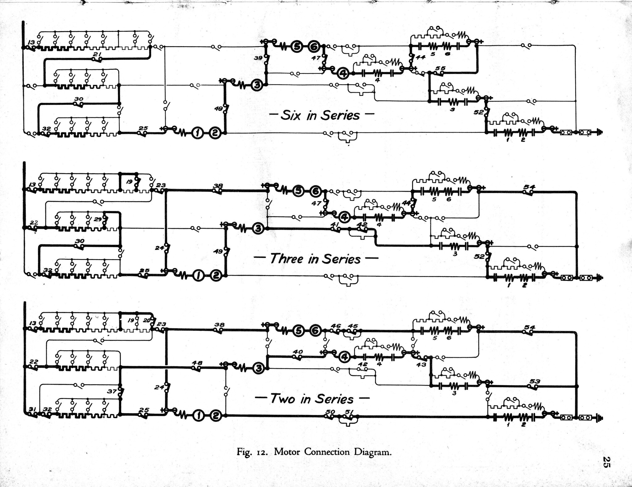
While I do not have a wiring diagram of the EP-3 Passenger locomotives I do have ones for their immediate predecessor, the C.U.T. P-1a. Obviously there would be differences but I’m sure there is crossover in the designs used:
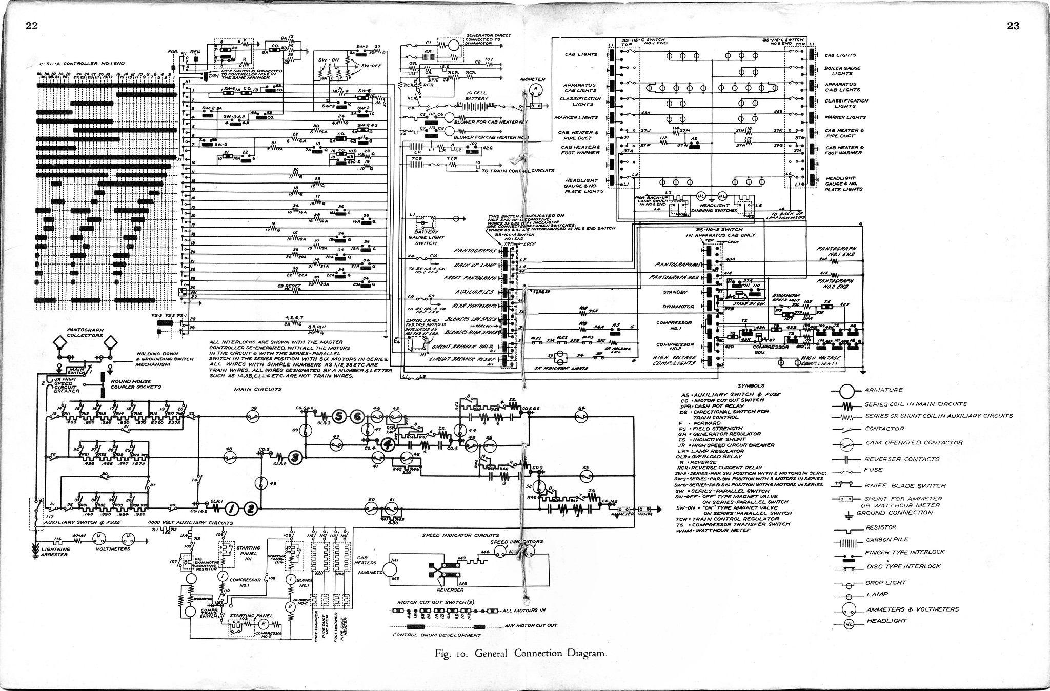 P-1a_General Connection by Edmund, on Flickr
 CUT_P1a_layout_0002 by Edmund, on Flickr
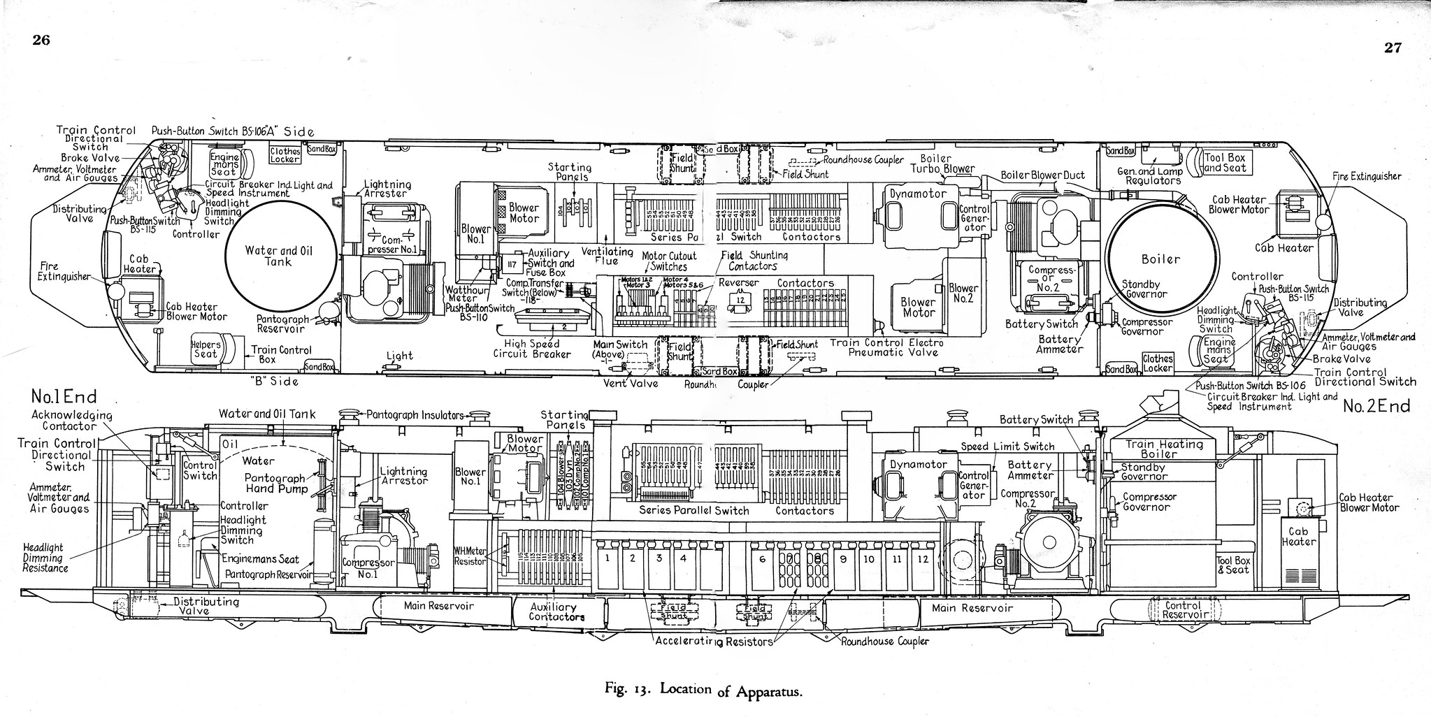 P-1a_General Apparatus by Edmund, on Flickr
There is some excellent background information about New Haven’s pioneering electrification here:
Hope that helps.
Ed
1 Like
Huh! Is the switching between AC and DC done while the locomotive is running in an unpowered section?
NH EP-1 (NJICB/Tamac 1982)
1 Like
My information comes from a paragraph on page 79 of When the Steam Railroads Electrified [Middleton, 1974] “Control circuits permitted transition from A.C. to D.C. operation without stopping. Interlocking controls prevented current-collection devices from being in contact with the D.C. third rail and the A.C. overhead at the same time”.
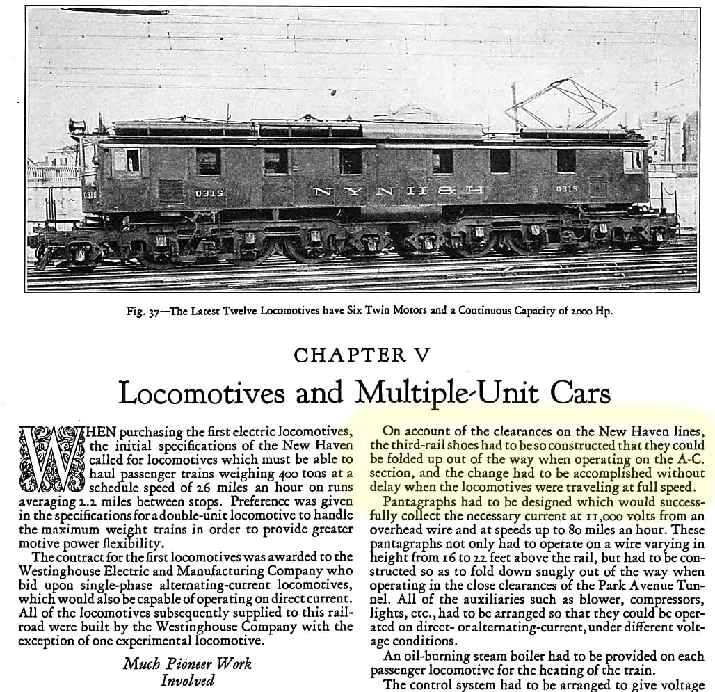
The above is from a June, 1924 publication from the Westinghouse Corporation.
I’d sure like to see what the exact procedure is. Since, I believe, there’s no way to ‘disengage’ a third rail shoe the locomotive would have to be clear of any third rail structure before raising the pans.
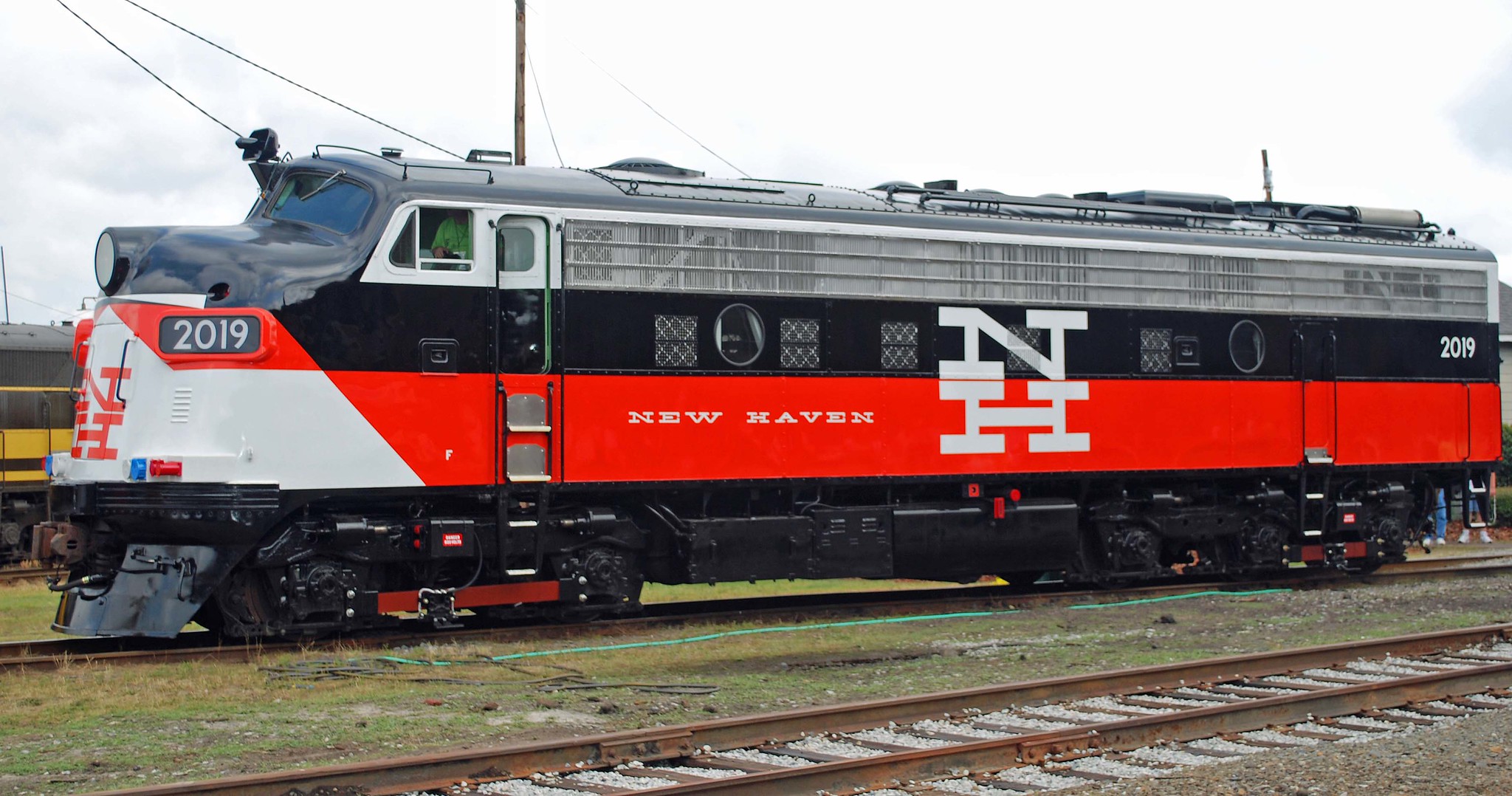
I believe the TurboTrain and the FL9s could also be ‘switched over’ on the fly (not to overhead, of course, but to the internal generator or turbine. I believe the FL9s also had specially designed third rail pickups that could run on under- or over-running third rail.
 NH FL9 #3012 311013 (4) by Rick Wright, on Flickr
The original FL9s did have a small DC pantograph for negotiating the GCT third rail gaps.
Cheers, Ed
2 Likes
Suffice it also to say that this isolation was not always effective, and transfer to (or from) 600VDC could be accompanied by a variety of bangs and fires. In fact more than one of the ‘lightweight trains of the future’, which did not use 11kV, had this trouble – Ed could tell that story better than I could.
2 Likes
Thanks for sharing these documents with me, have you got any more documents containing detailed operation of the pantographs from the same issue of Westinghouse cooperation from 1924 and also clarify whether new haven electrics used tap changers with universal motors under ac and rheostats under dc with third rail and universal motors as universal motors could run on both ac and dc.
Thanks
Regards
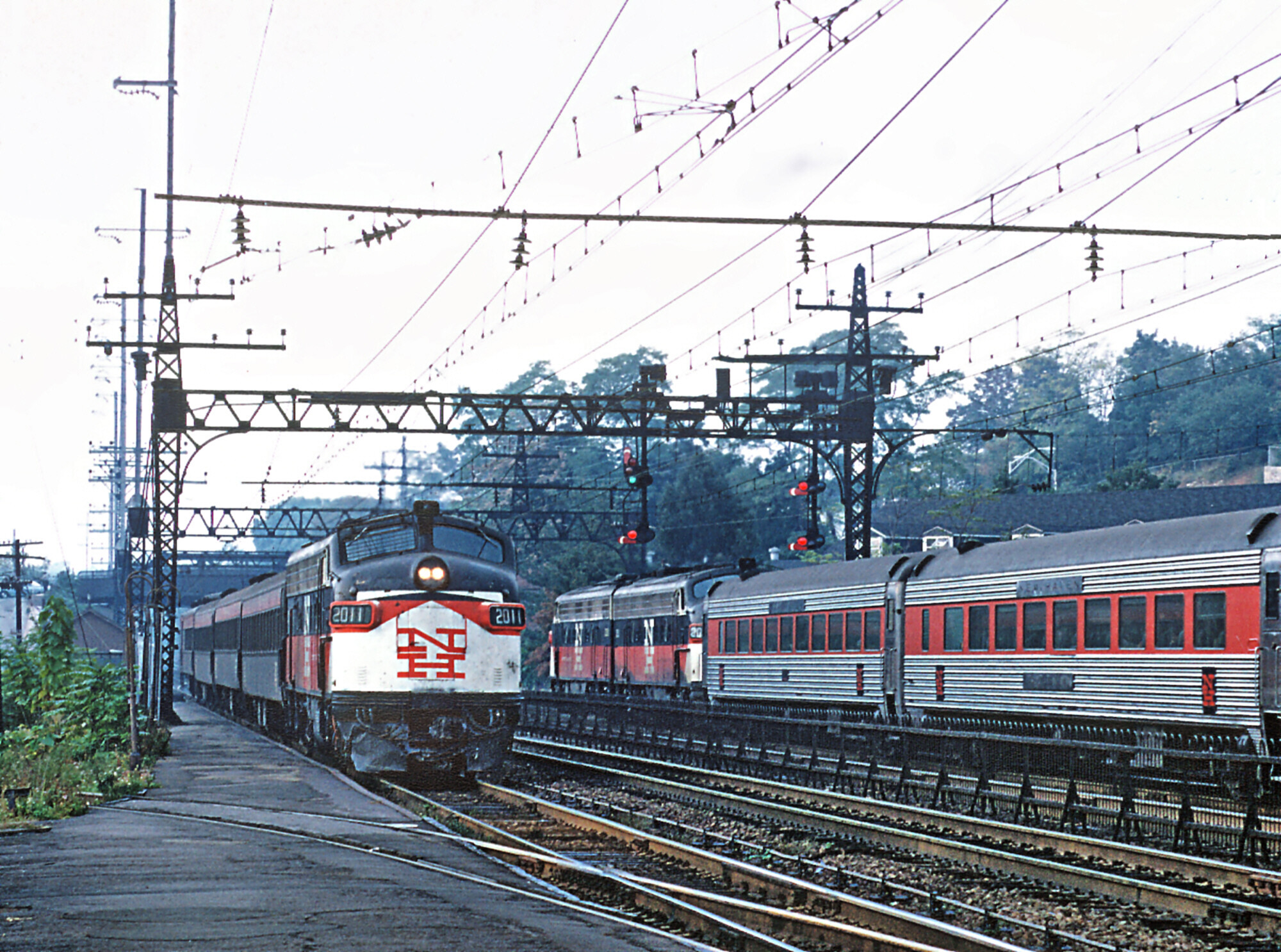
The FL9s under the New Haven would switch over to diesel immediately after exiting the Park Avenue tunnel. I have occasionally taken FL9s to Penn Station–i’m not sure if they used the LIRRs third rail but if they did it would require the third rail shoes to have the flexibility to use over rail collection.
1 Like
This is off-topic, but I didn’t want to start a new thread on a non-New Haven specific site. The New Haven had a mixed train that left Penn Station at 8:15 PM in the late '60s. It was a remnant of the Montrealer. For a while the Pennsylvania and New Haven continued the train as a Washington Springfield train, but then the Pennsylvania discontinued the through operation. The New Haven had an 8:00 GCT-Springfield train that got most of the passengers but apparently couldn’t get permission to discontinue this train so it left Penn Station with several express cars and a single coach. It stopped at the Oak Point yard in the Bronx where piggy back cars and a caboose were added.
1 Like
1 Like
The FL-9s originally did have double-sprung third rail shoes and could use either NYC or LIRR power. But they had to be maintained, with spriing cojmpression watched carefully. And the third-rail had to be in the correct position, also. A few broken-off third-rail shoes and the need to use diesel power for the affected trains in-and-out of GCT, (with a resultant smoke .cloud in the Waldorf Astoria Hotel Ballroom) led to either replacing the New Haven shoes or modifying them (I think some of both) for NYC under-running only and banning them from Penn Station. GG1s solved that problem for Amtrak’s use of the New Haven line. The FL-9s used by Amtrack had over-rinning shoes applied for LIRR thied rail when Amtrak opened the West Side line for passenger service..
1 Like
I read that when the FL9 batteries started to fail, they would leave the diesel engine idling in GCT/tunnels for fear on not being able to restart them.
I personally saw that quite a few times. It did not help that the 567s were poorly maintained and produced a bank of heavy white smoke. They would be spotted under pavement gratings to let the smoke out to street level.
Yes, that made the problem even worse. Obviously, if third-rail power was available toi the FL-9,.the batteries would be recharging.
Much appreciated for all your replies, I believe FL9s even had Hancock 4700 air whistles before they received horns so when exactly did they get them and given that all of them received 645 packs in 567C/D1 engine blocks which have 645 exhaust notes at notch 8 can anyone discern as to how they sounded when they had 567 assemblies as I have heard some non-rebuilt 16-567C/D1s on YouTube on ships and as stationary power plants that didn’t receive any 645 assemblies so would they have sounded similar kindly share your views.
cheers.
As built, FL9s had the Hancock whistle mounted at the top of the windshield pillar. The Amtrak FL9s rebuilt by Morrison-Knudsen lost the whistles in the 1978 rebuild. The Metro-North units lost theirs as rebuilt by and for Conrail and Metro-North.
An FL9 with its original power assemblies sounded a lot like an FP7 or GP9.
On one trip on #48 in the late 1980’s, while the train was being serviced at Albany and new power attached to the head-end, I kiddingly asked the engineer if he “wanted some company up there” in the cab of the FL-9. To my shock & surprise he not only let me into the cab, he let me stay there all the way down the Hudson! I even got to blow the horn a number of times; it was the thrill of a lifetime. This engineer was within days of his retirement and yes, he told me, he had known Bob Butterfield.
The fireman spent the time sitting in his seat and calling out the signals to the engineer. The engine rode well enough on the jointed rail. At Croton-Harmon, I returned to my roomette; there was no reason to attract attention at Grand Central.
Consequently, I’ve admired and had a soft spot for FL-9’s ever since.
1 Like