Last night I realized that the six pin IC sockets won’t work for tri-coloured LEDs so I have ordered eight pin sockets. The tri-cloured LEDs require at least seven circuits to show the proper indications.
Dave
Last night I realized that the six pin IC sockets won’t work for tri-coloured LEDs so I have ordered eight pin sockets. The tri-cloured LEDs require at least seven circuits to show the proper indications.
Dave
Okay gang, here we are a month later. The ladders and platform materials finally arrived so I have been able to construct an N scale test signal:
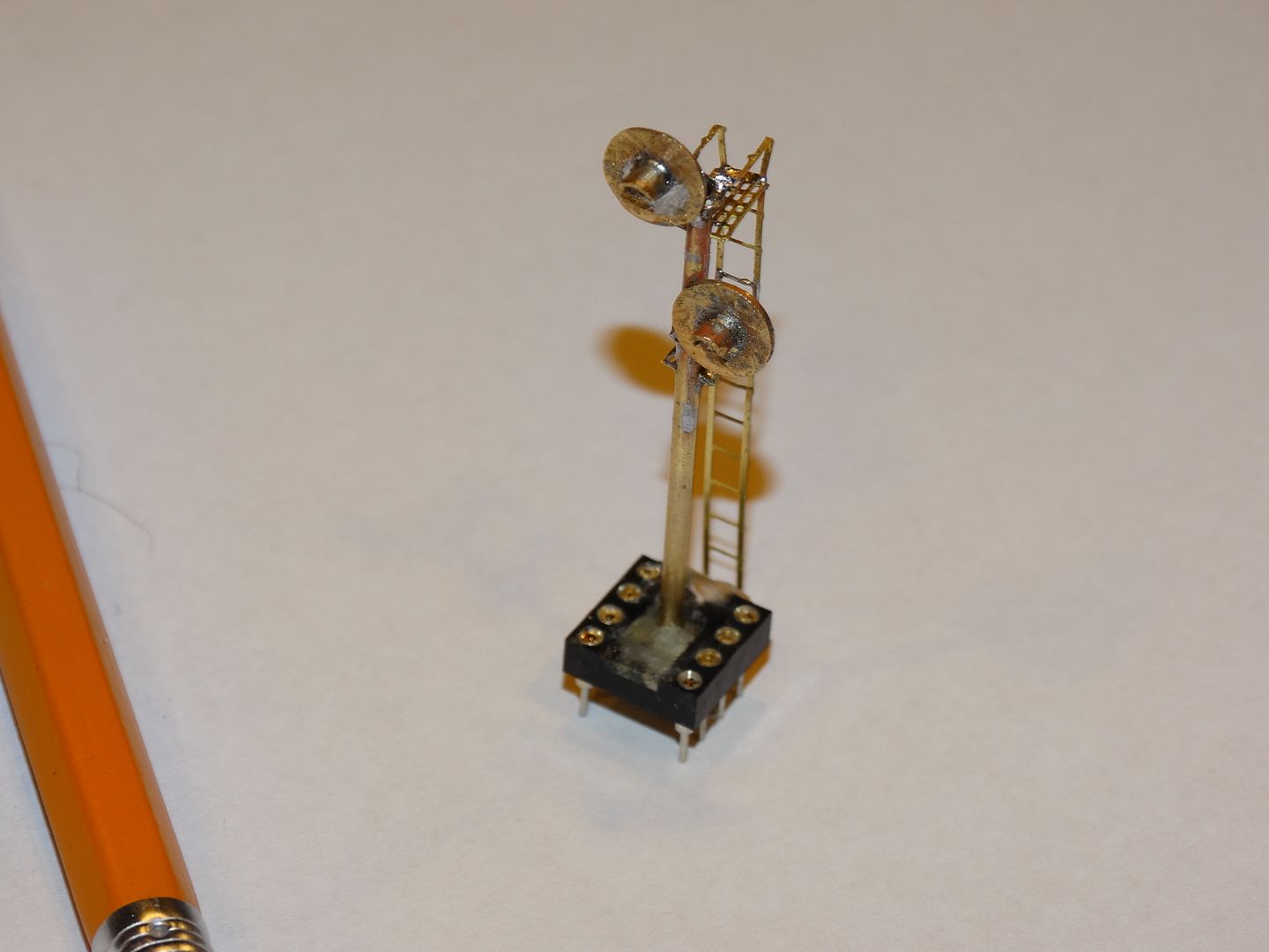
As I said previously, the heads are a little oversized, but I will leave it up to my friend for whom I am building the signals to decide if they are acceptable. Remaking the heads would actually not difficult at all. They are basically just brass washers and tubes.
FYI, the ladders and the platforms are from Gold Metal Models. The platforms are made from their ‘Atlas/Con Cor 40’ Boxcar detailing set #160-15’, and the ladders are made from their ‘Freight Car and Industrial Ladders #160-25’.
The eight pin IC socket will fit into an identical socket which will be mounted below the surface of the layout. That will allow the signals to be removed as needed when work is being done on the layout. The reason for the eight pin socket is that we want the signals to be tri-coloured, and we want the two heads to be able to operate independantly. The HO signals that I showed previously in the thread were originally designed for just two colours, hence the six pin sockets, but we have changed our mind on those so they will be three colours as well.
I have to confess that making the first signal took far longer than I had anticipated, mostly because of my own ineptitude.[D)] I managed to solder the lower signal head on side ways and upside down three times before I got it right.[banghead][banghead][banghead][(-D][(-D][D)] Then at one point I was simply trying to adjust the distance between the upper and lower heads. I needed to move the lower bracket up about 1 1/2 scale feet but it wouldn’t budge. I guess I pushed a little too hard on the lower signal head mounting bracket and everything including both heads and the mounting brackets
May I ask where you found the 0306 tri-colour LEDs?
Barry
Hi Barry,
I got the LEDs on eBay. Here is the listing:
However, I have decided to use different ones based on RRMel’s recommendations. The LEDs above come pre-wired which is great, except that the wires are quite thick when compared to most pre-wired LEDs. The thicker wires won’t fit inside the poles on the double head signals. Single head signals are okay.
These are the LEDs that I’m going to use:
https://www.digikey.ca/product-detail/en/bivar-inc/SMTL4-RGY/492-2173-1-ND/6217520
The LEDs are larger but they will still look as though they are just part of the case on the back of the signal heads. They are not pre-wired unfortunately, but that allows me to use magnet wire which is small enough that I can get six wires down the posts even for the two LEDs on double head N scale 1/16" posts. (The posts will serve as the common lead for both LEDs.) Feeding the wires will be a challenge on the N scale signals. It shouldn’t be a problem on the HO signals.
I will offer one caveat regarding the N scale signals. I haven’t tested the new LEDs to see if the light will project properly through the hole in the target. I’m going to test one tonight and I will let you know. They will be fine on the HO scale heads.
Dave
The SMTL4-RGY has increased in price since I bought mine. I bought mine from Mouser for $1.27 each about a year ago. Mouser was 3¢ each cheaper than the other sellers. As I remember there was a pretty good price break at 25.
I soldered #36 Litz wire to the SMTL4-RGY off eBay, 20meters of four colors for under $7 free S&H.
Soldering the #36 wire was a piece of cake, I didn’t ding any soldering them.
EDIT:
Dave, I really like your socket mount!!!
Mel

My Model Railroad
http://melvineperry.blogspot.com/
Have you had a chance to try the new LEDs in the n-scale searchlight yet? I have brass coming but have not ordered LEDs yet. Barry
Hi Barry,
I haven’t assembled a head with the SMTL4-RGY LEDs yet but I have tested them by holding a lit one to the back of an N scale target. The light was quite visible even without a lens in place. I plan on using a piece of acrylic rod polished on both ends and then epoxied in place to act as a lens.
I’ll assemble one within the next couple of days and post some photos.
Dave
Hi Mel,
Thanks for catching that! I smoked one already![D)]
I also had a devil of a time getting them to work at first! That was until I realized that I had them wired wrong. I misinterpreted which contact was the common.[D)][|(][D)][:$]
IIRC, the resistor values that you posted were based on a 5 volt power supply, therefore with the resistors in place the voltage should be correct. Correct?
Dave
Based on the specs for those LEDs, for a 5V power supply I’d suggest 390 ohm for the red and gree, and 220 ohm for the yellow. If the green appears too bright, try a 470 ohm. Differing values to make them appear approximately the same brightness. All values keep them well under the current limit. If you want to just use one value resistor for all of them, 330 or 270 would be good.
BTW, these seem to be close to the colors of those RR CirKits ones, with the proper bluish-green for a railroad signal. They are also about 4x as bright, I didn;t look to see if they have one with these wavelenghts of light but at a lower brightness
https://www.digikey.ca/product-detail/en/bivar-inc/SMTL4-SRGY/492-2193-1-ND/6217527
&nb
Hi Randy,
RRMel, who recommended the Bivar SMTL4-RGY LEDs, suggested using the following values to get the brightness of all three colours to be similar @ 5 volts:
Red - 1K ohms
Green - 560 ohms
Yellow - 180 ohms
Dave
Randy
The values are for my Eye after cataract surgery (6 months) so I think the colors are pretty close to equal.
I ended up with the following @ 5 volts using my Arduino power.
2ma for red
12.5ma for Yellow
4ma for green
The Yellow takes more current to equal the Red & Green brightness
Mel
My Model Railroad
htt
I just built my first n-scale signal target. I think I need to build a couple of jigs to make things easier.
I would post a picture but I can’t figure it out right now.
Barry
Hi Barry, I’d like to compare notes on how you made your targets. Mine are pretty much freehand so there are minor variations from one to the next, but they are so minor that nobody will notice.
There are instructions on the top of the General Discussion page on how to post photos. Basically, you will need a photo hosting site like Imgur (free) or Photobucket (small fee). You transfer your photos to the hosting site, then copy the image address from the ‘Direct’ or ‘Direct Link’ line beside the picture. When you are writing your post you will see an icon that looks like a mountain with the sun. Once you have copied the photo address, click on the mountain icon and paste the address into the appropriate line in the pop up window. Then hit ‘Okay’ and the picture should appear in your post.
Dave
Does anyone make N scale riveted gusset plates?
I have volunteered to scratch build an N scale three track signal bridge for a friend. I plan on using brass. I can make gusset plates from brass sheet no problem, but adding the rivet detail could get really tedious really fast.
Any suggestions?
Dave
I
I’ve just been using a calibrated eyeball with a scale ruler. There will be variations, but then again, if I’m happy they’re good. I think I copied your method. File out a #4 washer, solder in a 1/8 tube, file a 1/16 tube to a sunshade (ish) shape and solder that into the target assembly. The assembly is soldered onto the mast. I should have the LEDs this afternoon. I need those to determine where the searchlight is attached to the mast. Solder #36 magnet wire to the LED and feed those into a hole on the mast and out the bottom. Attach resistors and I should be good to go. I still need to get ladders and platforms.
I’m kind of designing on the fly and assessing as I go. I grabbed a copy of the GRS type SC doc that Mel (I think) posted. That has been very useful. I will need to clean the brass before I paint them. I’ve been using acid flux when soldering. The solder itself is SAC305 0.020". My jig is just a piece of hickory with holes drilled to make holding things easier when cutting and filling.
Barry
WooHoo. I figured it out. Looking at everything under magnification I think I should finish filing the sunshield after attaching it to the mast.

Hi Barry,
That’s how I do it. I solder the brass tube that will be the sun shade into the larger tube and then cut it off a bit longer than needed. The next step is to shape the sun shade with the cutting disc and then file the burrs and excess solder off with a needle file. Once the target is presentable I cut it off flush at the back so the LED can sit right up next to the back of the target.
These are similar to the discs I use for both cutting and shaping the brass tube. They cut very quickly:
One other thing I do is use a small pair of vice grips to hold the washer when I’m doing any cutting. That prevents things from getting hot enough to melt the solder, and it keeps my fingers away from the cutting disc.
Dave
I file by hand and cut the tubes with a jeweler’s saw. That saves my fingers a lot of grief. I chew them up enough when woodworking. I think I like the slightly slower pace and it gives me better control.
Barry
Target mounted on the mast.