I am considering dividing my 10 x 12 loop into three different blocks for future considerations. Do I remove the way I have it wired (just simple, from the A on the transformer to some feeders) and treat each “block” on the loop like a siding by soldering to the center rail, to a toggle switch, back to the terminal strip. My thought is to be able to pull trains out of a siding while one waits to go in off the main line and I also want to run two trains at once using a block signal eventually. Obviously its all conventional mode, Thanks.
Why not use single-pole-double-throw-center-off (SPDT-CO) switches, with the wire to the center rail on the common (center) terminal of the switch? That way, if you want to start using a second transformer, all you have to do is connect it to the switches.
Whether the A terminal is the right one for the center rail(s) depends on what transformer you have.
Bob thanks for the reply. I’m using a postwar ZW. Just for what I’m currently doing with just the one loop, I understood it to connect the U to an outside rail and the A to the center. Basically I just went went from the A to a terminal strip and off that around the track connecting to feeders every so often. I powered the terminal strip at the begining so I could power my sidings from single pole switches to turn them off and on. Whether or not that’s right or wrong I have no idea. Guess that’s why I spew my confusion to you all.
I say it now that I probably won’t introduce a second transformer only because I dont think I will need it based on the size but you never know. Thanks again for any advice, I need it.
I use post war ZW and divided into blocks using fiber pins and just interrupt the power with a on/off toggle switch to disable certain blocks. Having the main divided into blocks was a lifesaver when I recently had a switch go bad. The switch was in block two and when the train entered the block it died. Had I not been divided in blocks, the entire loop would have been disabled and the troubleshooting would have been ten times worse.
I also have a postwar ZW and have my layout divided into blocks with fiber pins in the center rail. I use atlas selectors to control the blocks. Slide the block switch on the selector up for ZW post A, down for ZW post D, center position is off.
Let me get this straight. I currently have a buss line going around connecting to feeders. I guess my main question is do I now divide the loops into “blocks” insulating the center rail, remove the buss line and feeders and treat each block like a siding? Meaning soldering a wire to that block and run it to a toggle switch back to the terminal strip. Or do I leave the buss and feeders and solder another wire back to the toggle to the terminal strip? Sorry for the confusion on my part.
Each block’s center rail is wired only to its switch. The switch connects it to the transformer’s output terminal. You can use single-pole-single-throw switches, which allow you to have each block connected to the transformer or not; but, especially since you have a ZW with two outputs for running trains, I recommend that you use single-pole-double-throw-center-off switches so that you can have three possibilities for each block: connected to the A control, connected to the D control, or off. The hard part is running the wires to the blocks (use no smaller than 14 AWG). Wiring the switches to the transformer is easy.
A (and D) are the right terminals for the center rail for a ZW. The reason I asked is that, with traditional single-output transformers, U should be connected to the center rail; and you didn’t mention which kind of transformer you had.
(Bus is spelled with one “s”.)
Much appreciated. Thank you.
Bob or anyone can you please explain the advantage for using the double-throw-center-off switches on just the one loop? Thanks for the knowledge!
It allows you to control two trains separately. Even with one loop, each train can be doing its own thing, switching perhaps. It’s not that useful if you’re the only operator–I find that I can control only about 1 1/2 trains at one time. But it does let two operators can run the layout. They can even run two trains around a single loop, by each taking control of the block(s) that his train is in or about to enter. (You would probably want a few more than three blocks for this.)
You did mention future expansion, which I guess might mean another loop. So, even if you don’t have a lot of use for two controls now, you might in the future. It’s hardly any harder to wire for two than to wire for one.
Many folks locate block-control switches on a (usually stylized) map of the layout. If you do that with SPDT-CO switches, I suggest orienting the switches so that the handles move east and west (left and right) rather that north and south. That way it’s easy to see which transformer control each block is connected to.
Bob, thank you very much! I greatly appreciate it.
I took bobs advice about a year ago with center off switches for the zw and it works great for block control.
What kinds of things do you take into consideration when setting up blocks? I chose 4 for no particular reason plus three sidings.
I would put block gaps at both trailing-point ends of a turnout, but not at the facing-point end, which makes the entire turnout the end part of the block at the facing-point end. That way, whichever way the turnout is thrown, the track not selected is always part of another block, and all of that other block can be used by another train.
Sounds good. One more thing before I head to the basement. Do I also need to attach a wire from the U post to each block?
The outside rails should not have gaps at the block boundaries (except for turnout control rails). But you may need more than one outside-rail feed for minimizing voltage drop, just as you might whether or not you have blocks. If you have a long block, it might need multiple feeds for its center rail.
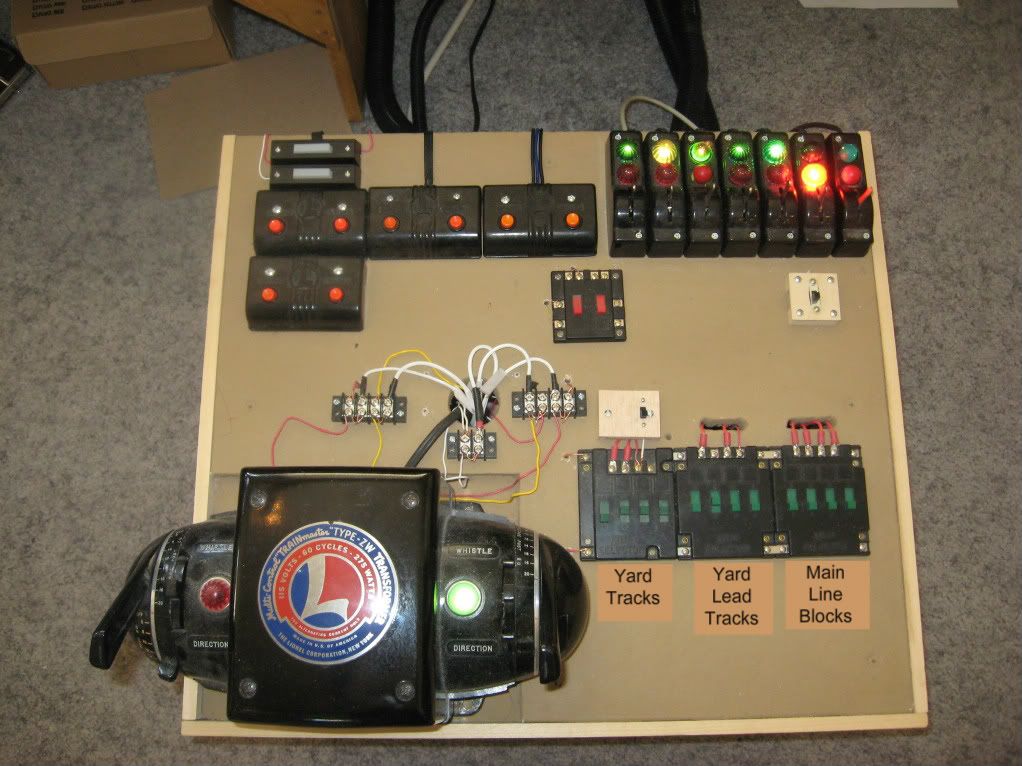
Where might I purchase lights to incorporate with my toggle switches on my control panel?
Radio Shack as a good selection of lamps and bulbs. You could go with a 12-18 volt bulb. Another choice would be to use an LED Radio Shack has an LED that runs on 12 volts ( the resistor is built in ) looks to be easy to mount to a control panel. They have red-green+orange, See link -
You might need a diode to change the AC to DC for the LED
or -
Go to Radio Shack and spend some time looking through the drawers of electronic parts - get some stuff and play around - you might make some mistakes, but you will learn as you go.
Steve
I am assuming that you want the lights to show which blocks are powered, like the scheme shown in the March CTT. That article seems to have been meant for two widely separated cabs. Since your two controls are on the same transformer, and I assume you are going to use SPDT switches as I recommended, and both operators can see all those switches, you have no real need for lights like that.
If you still want them, you can get these miniature-bayonet sockets at Radio Shack: http://www.radioshack.com/family/index.jsp?categoryId=2032294&allCount=5&fbc=1&f=PAD%2FProduct+Type%2FBayonet+Base&fbn=Type%2FBayonet+Base&filterName=Type&filterValue=Bayonet+Base
I recommend using them with number 53 lamps.
Yeah I figured the more lights the better. Makes it look like I know what I’m doing. [%-)] Thanks to you both.