I never have liked having feeder wires “exposed” and want to do my best to disguise them as much as possible. It has been mentioned in the latest (August 2010) issue of MR, in the Workship Tips column, that some drill holes through the ties and/or rails to make the feeder wire look like a rail spike. Does anyone have a link to a how-to video or detailed article how this might be done?
I had a different idea, though I don’t know how it would work out. For Code 83 and Code 70 rail in particular (I doubt this would work for Code 55), those are the three sizes I am dealing with, would be to use 26 or 28 AWG solid copper wire, drill a hole vertically through the entire rail from the top, tin the wire with solder, push it through the hole, add additional solder to fill the gap in the hole that wasn’t taken up by the wire, cut the wire flush, and file. Has anyone tried this kind of method? And if so, how easy is it? I know many argue once things are painted and weathered the track feeders that are soldered to the side of the rail can’t be seen, but for some reason, I can see them!
Thanks all.
Ken L
CEO & President, Pennsylvania & Allegheny RR, Circa 1953
A wholly owned, independently operated, railroad of the New York Central System.
The best way is to solder the wire to the bottom of the rail before installing it if you want them hidden. You could take the time to drill as you posted but why bother? You’ll still have the wire and solder connection that will show. If you have the track already laid just put the wire tight against the closest tie or even drill the hole angled under the rail to hide it the most.
Sounds like a great way to weaken the rail and make it unnecessarily vulnerable to kinking. Also, I doubt that my F-motors, with two big juice-hog open frame motors each, would be compatible with #28 or #30 feeders.
If you ever look at jointed rail used by things that draw power from either third rails or catenary, you’ll see big, ugly chunks of cabling (about equivalent in size to #22 stranded wire in HO) welded to the rail webs around every joint bar. Since those F-motors have pantographs…
Chuck (Modeling Central Japan in September, 1964 - partially under (virtual) catenary)
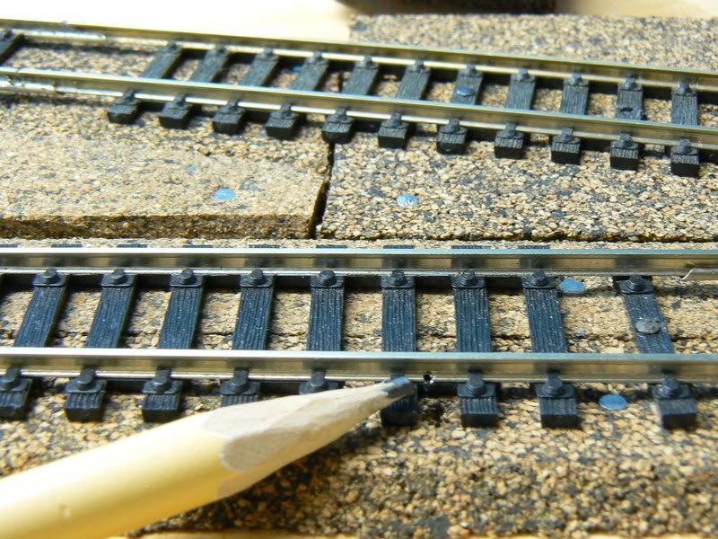
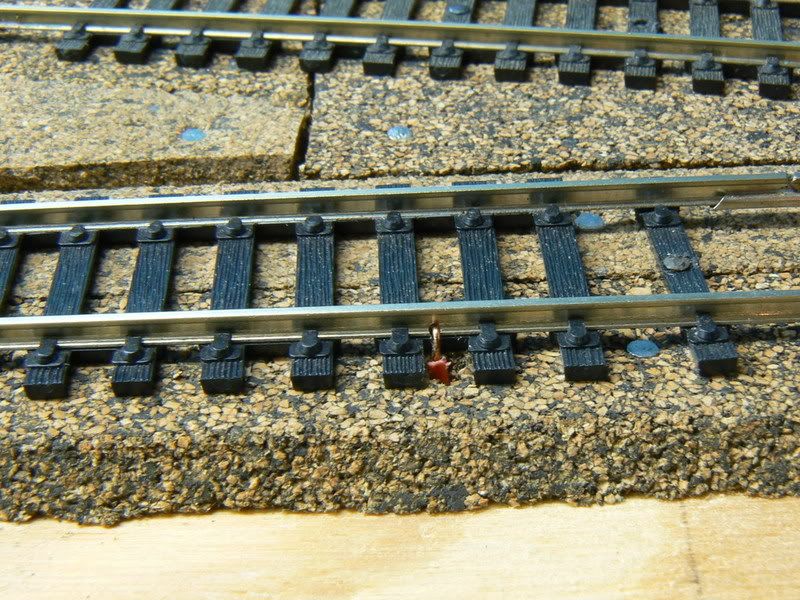
Drill a small hole through the tie, bend the end of the wire over to looke like a spike, stick the wire through the hole, solder the hooked over end to the rail.
I just solder the feeders to the bottom of the rail.
Gotta agree 110% with Chuck. I used 22 solid for my feeders and noticed more than a few have broken in the last 2 years. Go with 22 stranded. Build a little pile of ballast, dirt or dead grass up to hide it.
I started getting really picky about little stuff and it started taking all the fun away. [2c]
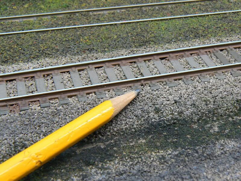
i have used the solid strand method explained in the mr book for realistic track and it is invisible. i use peco code 83 and drill through the tie plate next to the moulded spike.i have since painted all my track and i honestly struggle to find the feeders.
i have done strain tests on the feeders and i have not had any break on my transportable layout. it goes through quite alot of stress.