I just bought a second-hand Bachmann Spectrum 2-10-2, N scale, with DCC. It ran about 5 feet when the connecting rods fell off the middle wheel. I managed to put them back on, but now it won’t move. Lights work and gears turn but it is stuck. The middle wheel is not a driver on the track but it seems to be set to spin the rear and front wheel. There are 4 rods connected to it with a pin. The thing is, I can see the axle spinning around inside the middle wheel when powered. The question is: Is it an alignment problem with the connecting rods or perhaps do I need to glue the axle to the wheel to fix it? Any experience or input would help.
Bad alignment problem with the rods, but I suspect your problem is more ‘misquartering’.
On a real steam locomotive, each driver pair has the pins at 90 degrees to each other (hence ‘quartering’) with the pins on one side leading. It is made that way to be self-starting with double-acting pistons.
On each side, the side rods will appear to be in a straight line. If they are angled as in your picture, they will jam. The main rod (the British call it a connecting rod, as for an automobile engine) goes up to the crosshead, but it does not affect power to anything but the main driver.
On a model that is driven by an electric motor, the quartering does not have to be ‘exactly’ 90 degrees… but every driver pair needs have exactly the same angular ‘quarter’ within the play between the rod holes and the pins – this is only a couple of thousandths of an inch.
You are going to have to remove the driver pair that has the ‘slipping’ wheel and glue or stake the wheel in the correct position… whatever that is. You could use a quartering fixture, or make one using one of the unslipped pairs as a pattern. It would be a good idea, if you can, to check all the driver pairs at this time to be sure the quarter is correct and there isn’t any looseness in the fit of the drivers on their axles.
When in correct quarter, the rods will go on both sides without trouble.
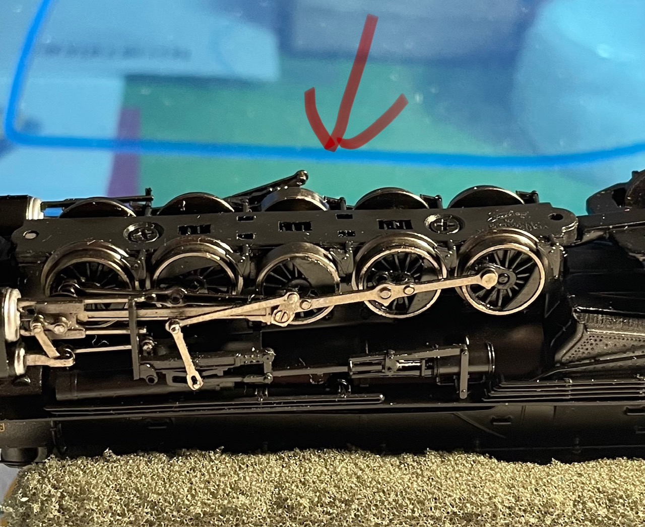
I’d like to see a pic of the other side. The eccentric crank near the point of the red arrow seems to be sticking straight down. Notice how the one on the side facing the camera is near the middle of the wheel.
The positions of the counterweights on the drivers are different. These have to all be in the same position on each side with the opposite side 90 degrees different.
I find it very difficult on N scale engines that have gears driving all axles to get the geared wheels positioned so that the side rods line up properly.
Since this is a second hand loco someone may had had the drivers our and not gotten them back in the correct positions.
Mark Vinski
Mark, keep in mind that on a toy, you don’t need precise 90-degree quarter. At least in theory you could line ‘one side’ up with a gear tooth on each pair, and then set the opposite side ‘wherever’ within a few degrees as long as the jig has them all precise to each other. Then putting the drivers back should give you precise registration when the gears are engaged.
My problem is not in the quartering of the drivers. It is getting the gears to engage the proper teeth when placing the drivers into the loco frame.
Mark
Well, I messed with it since that picture was taken, so it won’t look the same. Which way do those expansion links need to face to make them work?
I am not sure it is a quartering issue, but I will take it apart and see if I can align it correctly.
I’d still like to see a good pic of the other side. Look where the red arrow is pointing in the earlier pic. It sure looks to me like the eccentric crank is the wrong way around on the far side, but it’s hard to tell when we can’t see it all.
The position of the eccentric crank on a toy engine shouldn’t matter; the valve gear doesn’t ‘do’ anything real, so it just has to be free of binding. The links for Walschaerts gear have the curved side facing forward, so the reach rods can be a common length as the cutoff is adjusted. (Of course nearly all toy engines lack functional or even poseable reverse, so this is just for appearance…)
All that you’re concerned about now is getting the ‘quarter’ on the driver pairs to be common, so the spacing between rod pins matches the rod length (which is fixed by the driver spacing in the frame). That is visibly wrong in your pictures, but no amount of twisting or manipulation “to get the rods to look straight” is going to substitute for fixing the underlying problem(s).
You have to pre-rotate the driver pair so that the pin location is angled by the right amount, and then ‘roll’ it relative to the intermediate gear as it goes in – move it out radially relative to the axis of the intermediate gear if you need to get its bearings into the frame slots, but then continue to rotate it ‘around’ the intermediate gear as it goes down into alignment. If the drivers are all in relative quarter the ‘other side’ will take care of itself when the side you can see is right.
What I was saying about getting the gears adjusted is so that the pressure faces all engage when the pins are at the desired angle, so the rods don’t actually have to do any work.
Thanks. I will try my best to get them aligned.
The eccentric crank should point towards the middle of the wheel. The one on the far side (under the red arrow) appears to be 180 degrees off. That indeed is enough to cause a jam stopping the engine’s movement.
However, the rear driver on this side is sticking up a bit, being forced up by the connecting rod. At least on my HO 2-10-2, this isn’t one rod but a series, and it does seem to become misaligned like this pretty easily. I suspect if the OP gets all five drivers in line on this side, the other side will be fine too. But we’ll see, could certainly be one of the other issues suggested.
The eccentric crank only drives the fake eccentric rod and linkage connected to it, and Walschaerts or Baker on one side has nothing whatsoever to do with the other side of the engine anyway, It is supposed to be set leading or trailing the position of the main pin by 90 degrees, forward or backward; on a model it wouldn’t matter mechanically which – but reference to any prototype photo showing the valve gear will tell you.
I don’t think any “jam” involving the eccentric crank being set radially outward from the main pin would affect the other driver pairs as seen. If the main axle is driven by a gear or worm wheel, and the driver with the misaligned eccentric crank had a loose fit on that axle, you might get a loss of quarter that would throw things off – the thing to do is check quarter on all the driver pairs with rods off, then see if any driver is loose.
IMHO few things are worse to get running smoothly than a toy steam locomotive with ‘one-piece’ stamped rods. They need excessive clearance under the best of circumstances, and will bind if there is much loss of relative quarter.
I am ASSuming all the rods are the ‘correct’ length – exactly the distance between axles, rod-eye center to rod-eye center. I am also ASSuming that the axles fit reasonably into the slots in the frame without excessive fire-and-aft play, and that they are all blocked or sprung to run at the same ride height.
Again, if the driver pairs are all in relative quarter, which could be checked with a jig, when you get the pin locations lined up on one side the pin locations on the other side HAVE to be in alignment. If they are not then there is something else wrong with the frame or bearings. And if the rod eyes then don’t align easily over the crank holes, it suggests that a side rod is bent, or perhaps twisted, or the wrong length, and needs to be adjusted to be correct.
At this point I’d bite the bullet and carefully take down all the rods (get a nut driver if there are any hexheads for pins) carefully observing how they lap over each other. Inspect and correct driver quarter and axle alignment as necessary, then reinstall the rods on one side appropriately – be prepared that one or more may have been installed wrong by a butcher before you got the engine. If you checked quarter, the other side should now drop on correctly.
OK. If it were me, I would fix the easy mistake first - having the eccentric hanging down to below the top of the rails is not the right way for it to be. If fixing that doesn’t affect anything, then go on to other things. I know on my HO 2-10-2 I have had the siderods go out of alignment, and was able to get them back without having to disconnect them.
I tried adjusting the eccentric every which way, even after the photo was taken. It did not help. I still have not tried to line up all the holes in the wheels.
I think we got it fixed. I turned it over to my friend, Kim, from the N Track club. He has had the same loco before. So, it had three issues. One. the holes in the wheels needed to be aligned which fixed the quartering issue. Two, the middle wheel–which does not have a flange so does not come into contact with the track but does drive the rear and front wheels–has a hole into which the eccentric pin fits and holds the other rods in place. That hole had a split in it so the pin was coming loose. Three, the eccentric pin was spinning in the hole; it was not fixed in place. Kim squeezed the pin to give it some edges to an almost square shape. Then, after lining up the wheels he glued the pin in the hole. Now she runs.
He said he would recommend tapping the hole and replacing the pin with a screw if it does not hold up in the future.
Thanks for everyone’s advice on this.
1 Like
Problem with the eccentric? Who’d a thunk it? Glad you got it fixed.