My initial layout benchwork plans had me ducking under a thinner section of the board for access to an operating “pit” in the interior. I’ve done some reading on this and I know it is not ideal, especially for a permanent layout. My back and knees will rebel after a while.
So I’ve also spent some time trying to figure out if I can fit two large turning circles (not really peninsulas) on the ends (dog bone) to allow direct walk-in access. I think I’ve managed to sketch out an idea or two that will work, but I keep coming back to wanting the ability to run “thru” continuous mains rather than looping on the ends - so much so that I’m considering incorporating a 200’ Central Valley Model Works double track pratt truss bridge between the two peninsula ends of the “bone” to allow continuous running.
I realize I’m kind of fighting with myself here by doing this, and defeating the purpose of making the benchwork change in the first place. But on the other hand, it seems like it would be easier to only have to get under a 6 inch wide bridge than an 18 inch wide section of benchwork with 2x4 framing underneath. In my mind I’m rationalizing that the bridge is a better scenario if I have to have something to duck under.
Question: what am I not thinking about in this scenario?
The only concern that comes to my mind is that people accessing the interior could do a lot more damage to a model bridge if they hit it than would be done to actual benchwork framing. (My “people” are little people right now, but they will grow bigger and bigger.) But there are plenty of layout pictures out there of similar type set ups, so I know that people do, in fact, build layouts with this kind of access. Anyone build a duck under with benchwork or a bridge and regret it?
Question 2: I know people also build lift-out sections where needed. I’m just trying to evaluat
a higher layout will also make it much easier to work on using a chair with wheels. And of course, you can use the chair to slide under any duck under regardless of width.
What is the size of your room? I have a lift out section, but only because my space was limited (7x11 for HO). It does work well, but I built it nice and sturdy. Think of it as a door… and I’m pretty much a lone wolf. A plastic bridge would take quite a beating… If you are using DCC, reverse loops are easy to install and seemless in operation. So IMHO, avoid a duck under or overbuild a hinched liftout. You won’t regret it.
I once belonged to a club that has a duck under bridge, that layout is still going strong after 50 plus years. They did replace the original plastic bridge with a brass scratch built one. The bridge lifts up/out, so if you bump it, generally it just lifts up.
I am starting a new layout soon, in a large space, but still have decided in favor of a lift out. I prefer track plans where the viewer always has east to his right and west to his left relatitive to train movement, so I want to be “inside the giant circle”.
I would never build a fixed duck under. Even if most people choose to duck, you still need to be able to open those pathways.
My lift out will bridge a 36" long opening and be wide enough to carry 5 tracks, or about 1’ wide.
I have not made a final decision about lift vs swinging.
I had a duckunder [54 inches above floor, 36in long and 6in wide] for about 2 weeks. It then became a lift out. Its one thing to just duck down, and scoot forward. Now try it with both hands full. Gets old real fast.
It takes but a few seconds to remove or replace. But I found myself leaving it out and running a point to point most times
I built a lift-off section. The Central Valley bridge was in the middle, crossing a waterway, but I could have done as well without the bridge and water. It just looked nice. This could have been a duck-under, and frequently was, but I built it as a lift-off so that I would have that capability when needed.
This was between my main layout and an extension, so unfortunately it had to carry power. I built wiring into the lift-off structure, with plugs at either end. It worked fine, but was kind of a nuisance. That’s why I still used this as a duck-under most of the time.
I too would go with a fold-down or fold-up if I had it to do again. Make the whole thing rock solid so it will be used as intended and not more easily cheated.
This is a picture of the lift-off under construction. I built this from pink foam, layered, and surrounded with hardboard for protection. The superstructure of the bridge is not on yet, but you can see where the river will be. This is in HO scale, about a foot wide.
In the next picture, you can see the hardboard side and the superstructure. On these bridges, the superstructure is just for show. It looks nice, but bears no weight, and is easy to remove.
With the landscaping and water done, I think this came out pretty well.
This is exactly how I’ve done mine, only with the shorter Walthers bridge. The liftout is actually a U shaped piece made of 1x4s, so they provide a base for the scenery and protection for the bridge should it get left in place like a duck-under and bumped into.
Some of the detail design of lift-outs can mirror ‘best practices’ of module construction.
I recommend that you have a ROBUST set of feeders with appropriate plug-in on either end, and then feeders up to tee track rather than try getting continuity at the rail joints as well as precise running alignment.
i recommend you have some form of positive lockdown that actually snugs down to full correct alignment. And have four full contact points as close to the ‘corners’ as you can and make them fully and easily adjustable no matter how stiff you think your benchwork is. Do that once and keeping the joints lined and surfaced over time, and perhaps weather changes, is likely to be easy thereafter…
I built a hinged lift up as a teen that worked out very good. Because it only had a single track it was only 8” wide and used a single door hinge. I used two single flexible wires under the hinge side for track power.
I also interlocked the approach to the lift up as it was a 3’ drop to concrete. I’ve never been known for paying full attention to details like making sure the section was down and in place, probably saved several locomotives from disaster.
I have always had hinged swing-ups. For one thing, with the right construction and ‘sharp’ gaps where the rails must be that way, you can swing them up and down with impunity. It takes some thinking, some careful assembly, and the right hinges and supports so there’s no side-play or bending of the frame such that rail ends get snagged and lifted up out of the small plastic spikeheads. You can slide joiners onto one end prior to lifting, and then slide them back later.
One huge benefit that I figured out long ago is that the hinge, itself, if clean, will offer itself as a member of the electrical continuity components to the rails on the bridge. I put feeders from the nearby bus wires up to one of the screws , one screw per wire, and firm each screw down tight. Then, on the other side of the hinge, feeders under screws on that side run down under the module and up to the rails. You don’t need flexing wires here and there. This has worked 100% reliably on two layouts now.
David Popp featured one in Rehab My Railroad vol 10 & 11. He used plans from a Gordon Odegard article July 1990. The thing I like about the design is he uses contact switches on both sides of the swing up that control the power to the approach to the bridge. If the bridge is not in the fixed position, a train can’t get close to falling on the floor…unless you have keep alives.
Knees, backs and shoulders, for that matter, do not improve with age.
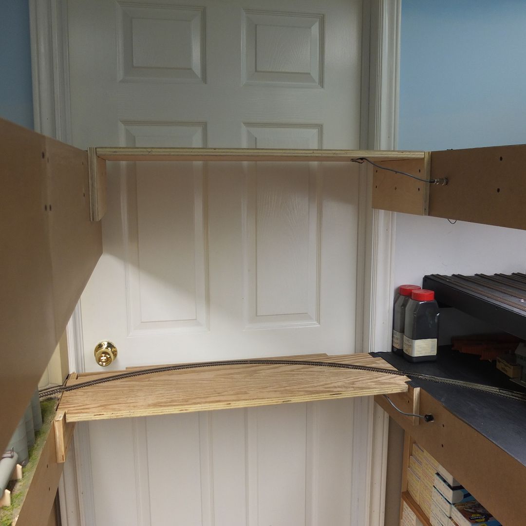
I have two liftouts at the entranceway to the layout. Because they’re liftouts, I wouldn’t waste money on putting a bridge on either, as the liftouts need to be stored when not in use.
I could, of course, leave the liftouts in place, and treat them as duck-unders, but I generally leave them out unless they’re needed for operations. Duck-unders are miserable if you need to move things in- or out-of the layout room.
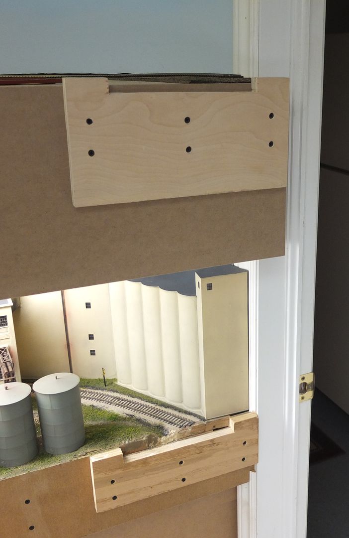
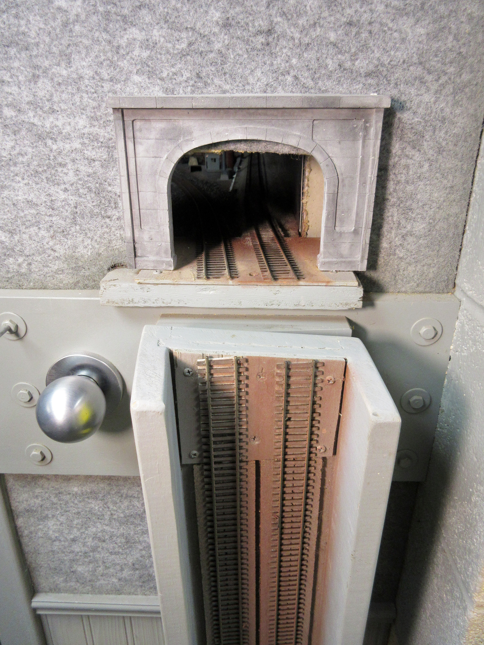
Here’s the two liftouts in place…
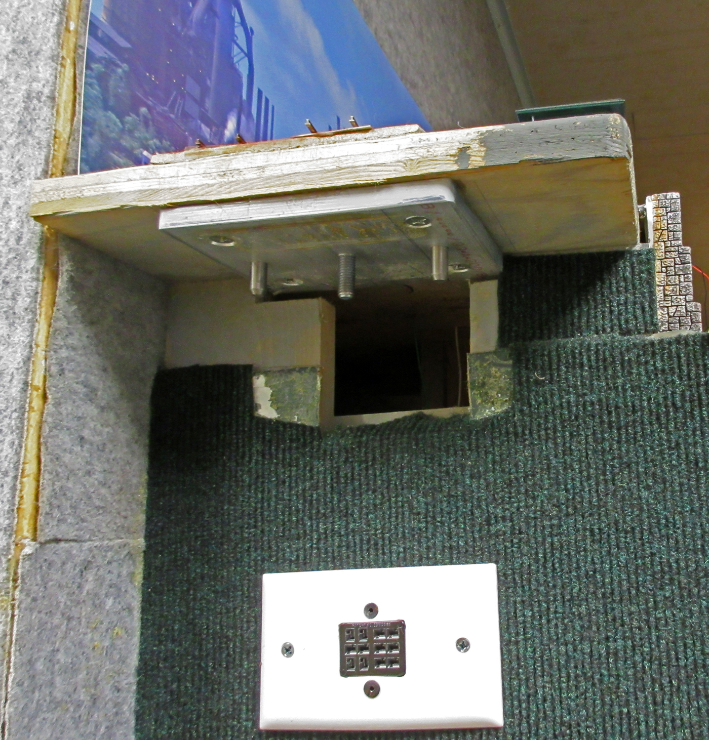
…and the brackets into which they fit to allow good alignment of the track at both ends…
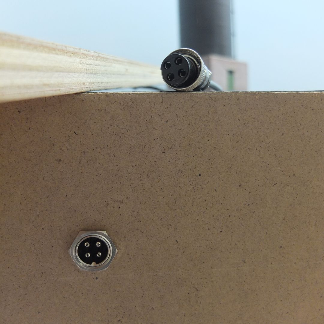
This indexed plug ensures that it’s always plugged-in properly, and allows for a non-powered zone for the tracks leading to the liftouts…
The fixed approach tracks on both levels and both sides of the opening are ended well-back of the opening, so there’s no chance of them being damaged when the liftouts are not installed. Nothing to get bumped or for clothing to get snagged, and the track ends are well-secured to prevent any movement that might be caused by moisture or temperature fluctuations (both very unlikely)…
Good info from all. My plywood is 36" above the floor. I plan to use one 2" foam board on top of that to lay track on. So my level is relatively low - a duck under is definitely not the way to go. Feeling a lot of love for a lift-out or hinge section. My book on trackwork from Jeff Wilson addresses both I believe.
I’m planning a lift up, when I get to doing my benchwork. No need to find a storage spot with it attached at one end. Lift up rather than tilt down, because if you have scenery on the section, it will be out of the way. With a drop down it would be sticking out into traffic.
The ones i have seen have the hinges on top disguised with a piece of painted burlap, to look like a plowed field. A good use for a grass mat also. Buildings or other scenery could be used to hide the hinges.
Noted from above, a keep alive makes a dead section of track to prevent swandives somewhat ineffective. Will have to think on that one as my most recent purchase has a lengthy one.
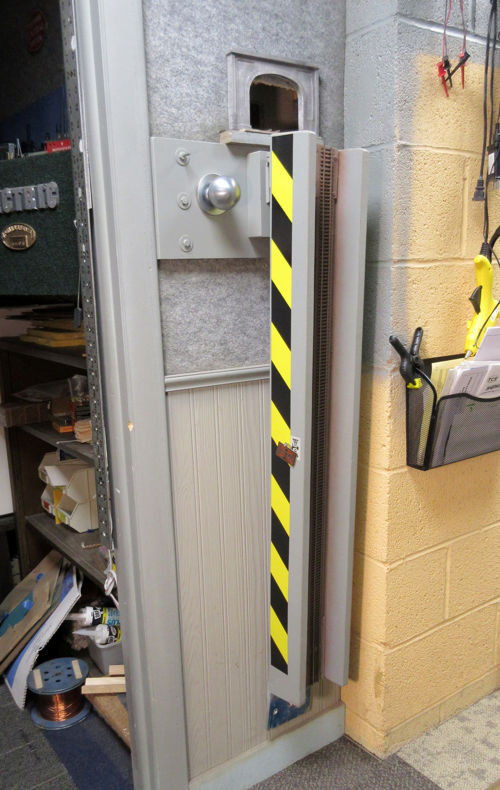
The other end has a 1/4" thick aluminum plate which has two index holes that align with ground steel dowel pins anchored to the benchwork on the open side. The middle hole engages a threaded stud to which I have a hand wheel engaged to support the bridge during operation.
There are two dog-point set screws with locking nuts that can be adjusted to “fine-tune” the level of the rail as it meets the gap.
I used to use that 12 pin cinch plug to pass-through track, lighting, signal and switch machine power but I have since disabled it. The plug also had a "
Guys, there is a fairly wide range of alternatives for concealed hinging of tilt-ups, if you really must have hinges. Personally I recommend an approach more like a plug door, where you pull it up out of precise alignment and then hinge away, instead of trying to make the hinge part of the alignment.
You could also arrange for the ‘lift-out’ to pull straight up a couple of inches, then pivot down clearing the ‘abutment’. Even cobbling hinges and brackets off the fold-down side shelf on a typing table might be a good start (as long as you keep the final vertical set into position exact, e.g, with four sets of adjustable wedges, not just slots).
You might start by asking Sheldon what he thinks would be the best heavy concealed or ‘face-frame’ compatible cabinet hinges. There is no reason multiply-articulated hinges could not be used either. In my opinion using top-mounted leaf or barrel hinges is just wrong on a great many levels, since there are better options.
(Of course, while I was fighting the forum software to make this post, Ed documented a perfectly good and relatively simpler thing, with all the necessary workable details…)
At my club, we built a powered lift out section that is 36" square. We purchased a 30" lift mechanism usually used for raising TV sets out of cabinets (and comes with a tethered remote control). For guides, we got one pair of 500 lb capacity 30" drawer slides (because they have no slop in their mechanism). We also got another pair of cheap 30" drawer slides as they are just there for protection of the layout.
The motor is mounted on one side only and has a plywood canterlever arm support to hold up the 36" square of layout. The heavy duty drawer slides are mounted on the same side as the motor and support much of the torque force from the canterlever arm. The remaining guides are located on the other side of the opening and keeps elbows from knocking down layout structures.
Since the layout track is about 43" off the floor (and goes up to 73" with the lift) and the movable section is about 4" deep, that only leaves about 69" of clearance (or 5’ 9"). Since I’m about 6’ tall, it’s a “nod under” more than a “walk under” (there are serveral club members that don’t have to duck at all). Still, it’s a heckuva lot better than getting down on your hands and knees to crawl under.