Progress this week…
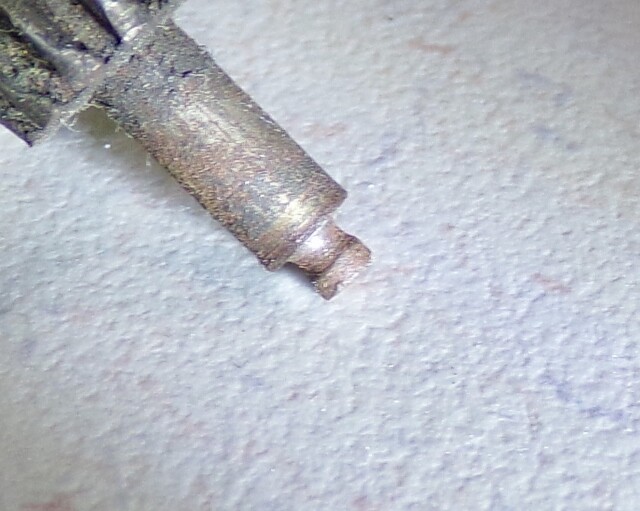
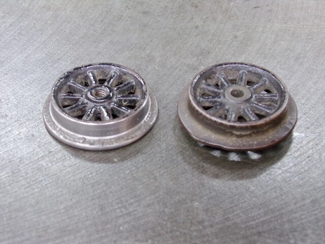
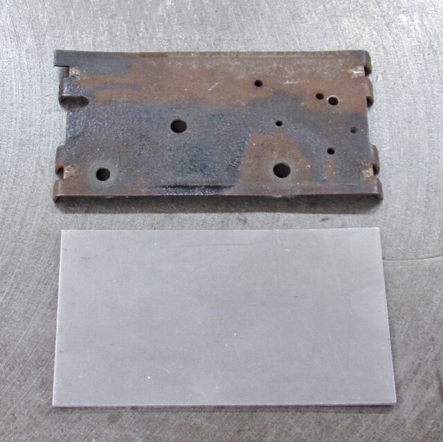
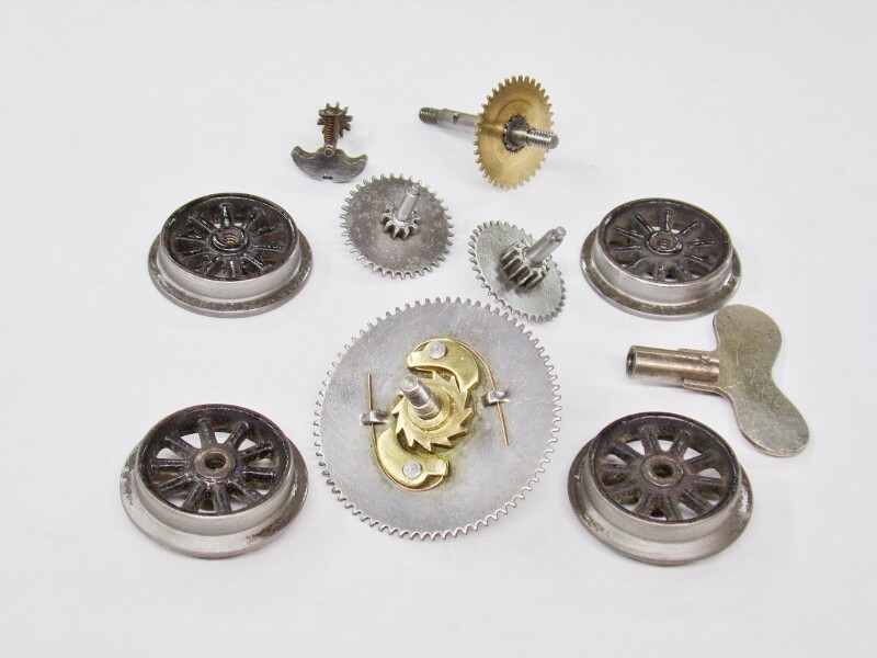
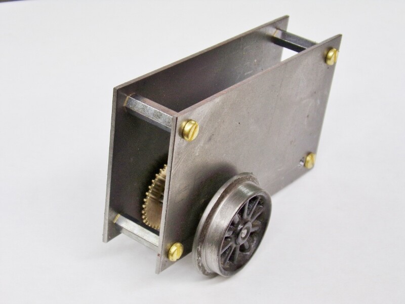
The salvaged motor parts soaked in Evapo-rust this week and cleaned up nicely. I also finished the mandrel needed to clean up the tread & flange on the idler wheels. Here are all the small parts ready to be put into a motor:
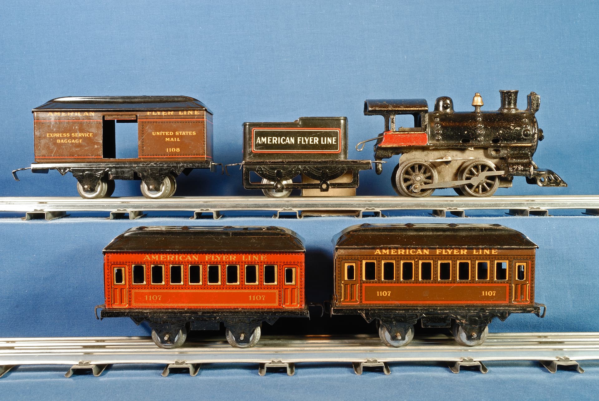
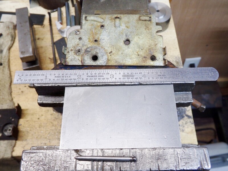
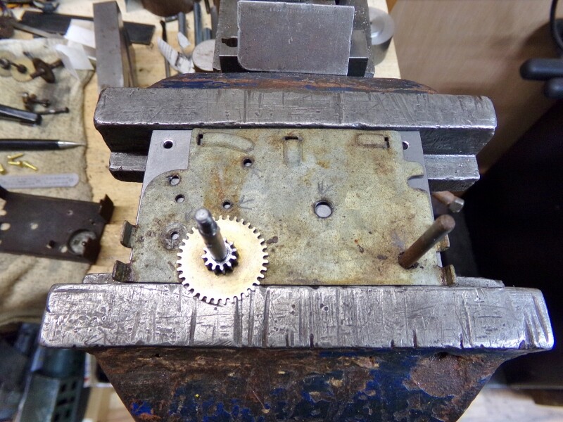
The next step is laying out and drilling the various holes in the sideplates that I had previously cut out. As I mentioned before, this is always a finicky process, so I like to have a block of time set aside when I’m alert and attentive to do this. I like to lay out the holes for the axles and the cross members first. This is a picture of one sideplate clamped in the vice, and a Flyer sideplate for reference:
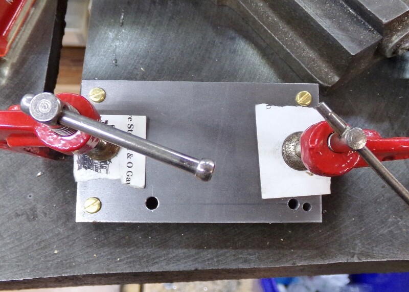
Once the axle and crossmember holes are drilled and centerpunched, both sideplates are clamped together and the initial drilling begins. I have some small 1" C-clamps that I use to hold both sideplates together for drilling. Doing it this way ensures that all holes line up exactly, as opposed to laying out both and drilling separately. I drill the crossmember holes in the corners first, and put machine screws in them as I drill them to keep everything in line. This picture shows the sideplates at this point in the process:
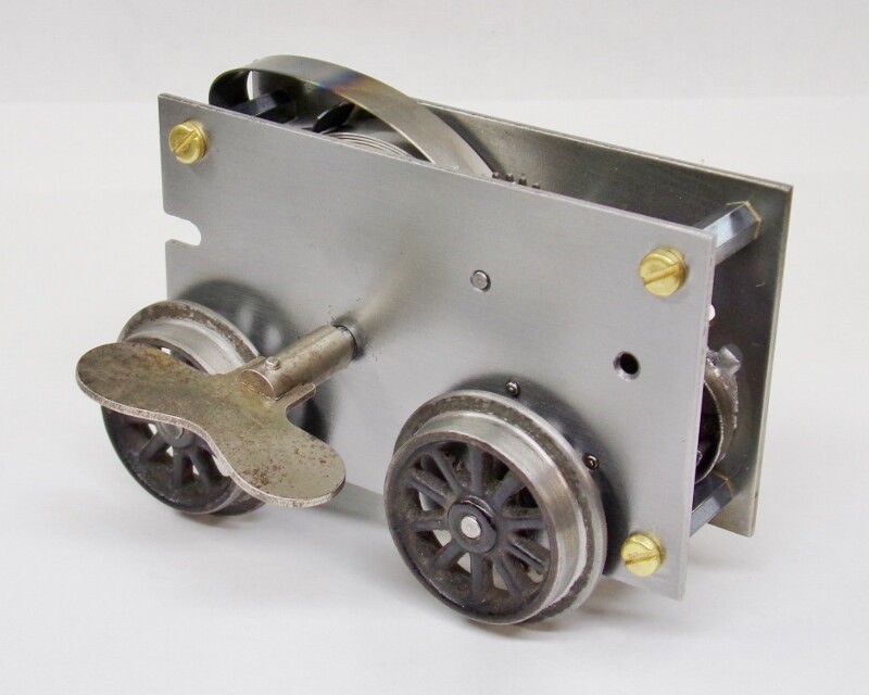
At this point, all the existing holes are de-burred and crossmembers prepared for a test assembly. For this motor, I am using standoffs for electronic boards that are tapped for 4-40 machine screws. The ones I have on hand are 0.750" long, but this Flyer motor needs to be 0.700" between the sideplates. I put each standoff in the lathe and machined 0.045" off one end. This will leave 0.005" end play for the various shafts so they rotate freely. With all of that done, I did the first test assembly to make sure everything was lining up so far:
Now it gets even more finicky… time to drill the holes for the intermediate shafts and winding stem. Using the drive axle and an old idler axle, I line up the Flyer sideplate and use a 0.5mm mechanical pencil to trace a circle for both intermediate shafts and the winding stem. This has to be done carefully to make sure the new holes are in the right position. Once this is done, the old sideplate is removed and each hole is carefully center punched for drilling.
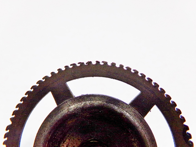
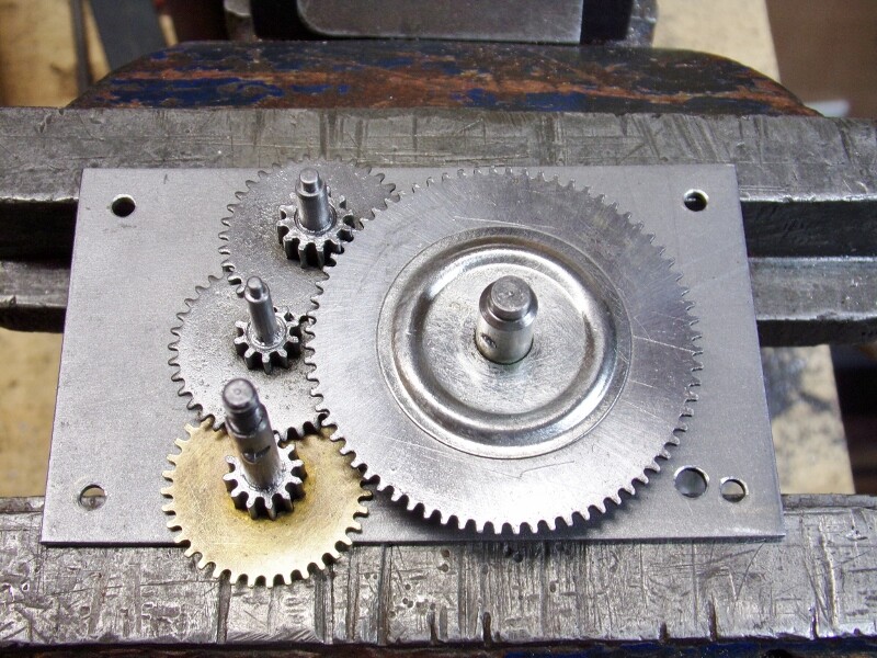
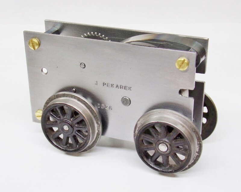
The plates are bolted back together for drilling. Each hole is a different size to fit the journal of the shaft. Again, this must be done methodically so that we don’t make a mistake - those can be difficult to fix, or they may even require starting over from scratch, so this isn’t a process to be rushed. Once the holes are drilled to the correct size, the plates are separated and de-burred. Time to load the parts and see if the gears mesh properly:
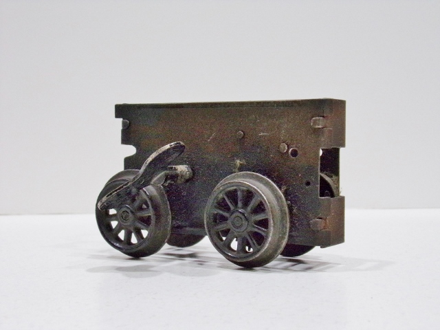
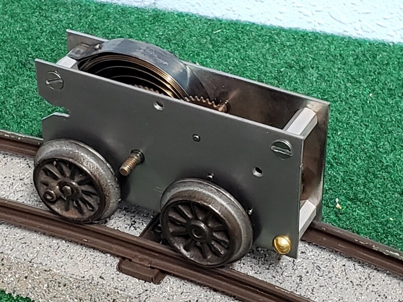
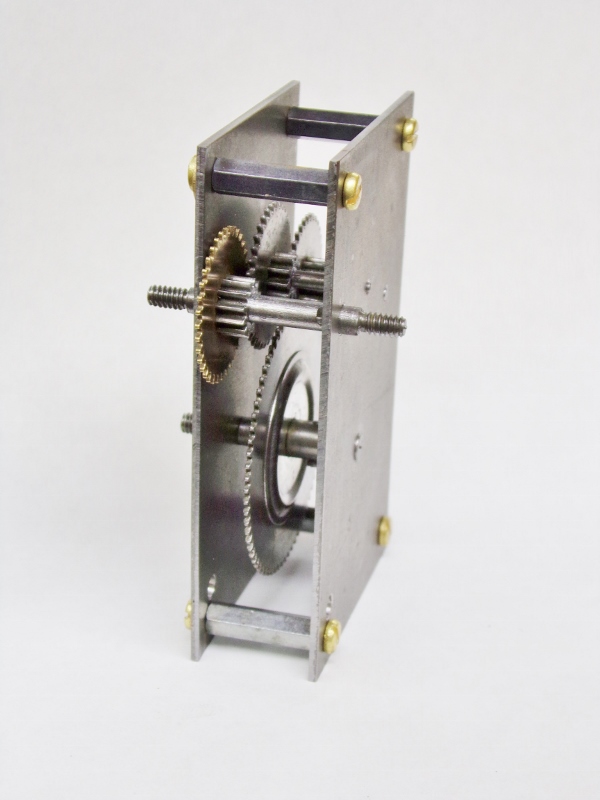
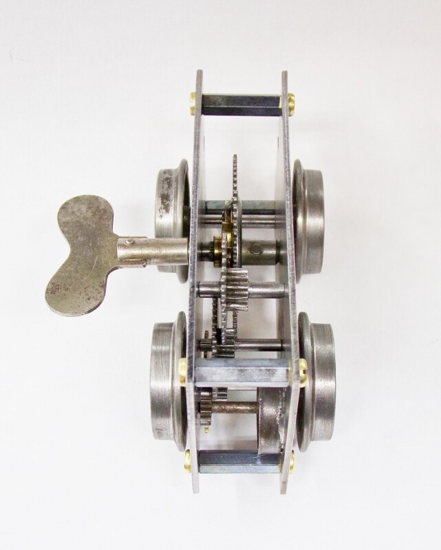
Fortunately for us, the gears look happy, so let’s bolt the sideplates together and see if everything will rotate - here is a view of it assembled, sitting on the back of the motor and looking in from the bottom :
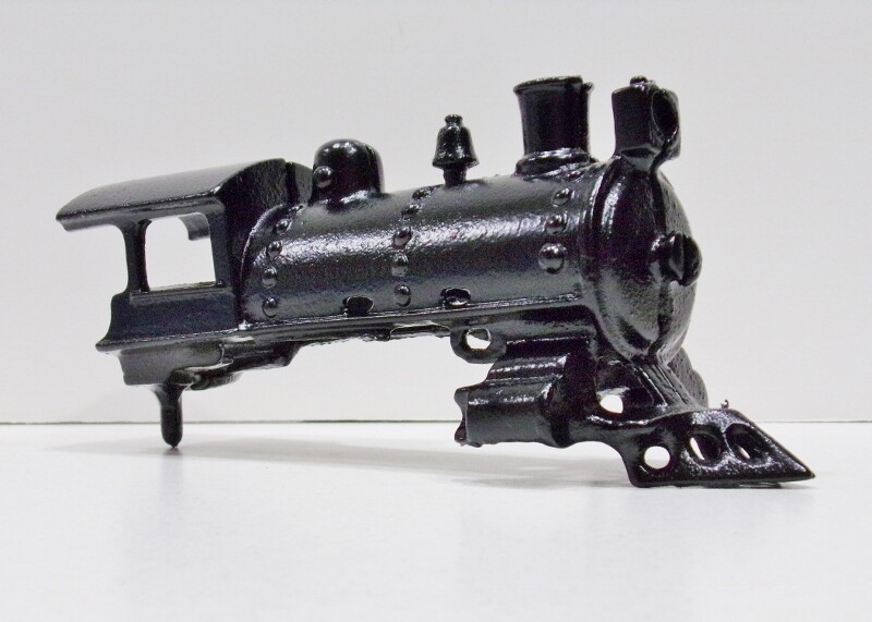
Everything is rotating smoothly, so work can continue when I get more time. The next step will be to lay out and drill the holes for the governor, then lay out and cut the slots & holes so we can mount the motor in the body.
That’s all for now…
James