Has anyone had good luck with any particular commercial uncoupler or a personal design? Thanks kindly-- Wayne
I had fairly good luck with the Kadee electro-magnetic uncoupler for N scale, back ages ago when kadee was in N scale as well as HO.
One problem- I hold down the button to activate the magnet at the same time I operated the throttle to reverse the train over the uncoupler.
One mistake- the instructions prescribed using a varnish to coat the magnet rails (which look like guard rails) to avoid electrical shorts. Instead of painting, I put thin tape on them for insulation. The thin tape was thicker than the varnish coast would have been, and car trucks fumbled a little when running over the uncoupler. Sometimes the tape made loco trucks lift enough to lose electric contact. I won’t do that again… but I do not think the N scale electromagnetic uncouplers have been available in 20 some-odd years.
I have several of the Kadee ones on my HO layout, they work best in places you may pass over a lot and not necessarily want to uncouple cars every time. The new version of Kadee #309 is designed to mount completely under the rails and ties, so there’s no problem with looks or snagging wheels on the magnet plates because they don’t stick up that high. I was buying and installing them at the time that Kadee was making the transition, so I have both versions, and both work reliably, just that the older one is more visible, which in some cases may be an advantage.
I agree with the other poster that holding down a button is a pain, but since it needs to be a momentary contact, that type push button seems to be the best solution. With my home made throttles, it hasn’t been as much of a problem as with the regular “speed knob” type.
I’ve got a Kadee unit as well, for HO. It works quite well.
One thing I would advise, though, is a separate power source for the unit. I tried it first on the same supply that ran my street and structure lighting, and caused a brown-out in town whenever I was uncoupling. Fortunately, I had an old wall-wart in the parts box. It’s 12 volts, 1 amp.
I have a few of the Kadee electric uncouples that worked well for me in the past so I decided I would use them on this layout only in a few key locations as I’m a cheap skate and didn’t want to spend the money for them. Then I recalled seeing one of the Allen Keller videos of how a guy wound his own uncoupling magnets using copper wire and a piece of the channel used to hang lighting fixture boxes. You wind the heck out of the copper wire around this piece of channel a few hundred times and then slip in a piece of styrene in the channel covering the wire. It holds everything in place. A friend showed me how you can use clear enamel over the wire same as used in some electric motor applications. So we make a bunch of these things for his layout and mine maybe 30 in all. Most worked ah ok but some weren’t strong enough and some didn’t work at all. (should have payed more attention in science class I guess) Well a few weekends later I was at a train show ans a guy had tow dozen of the Kadee magnets for sale at a great price. So I bought them all and being the nice guy I am gave all of my hand wound ones to my friend.
As far as holding the momentary button down couldn’t you accomplish the same thing with a stationary dcc decoder and or a relay? Maybe have one stationary decoder routed through a rotary switch or a bank of toggle switches So if you want to uncouple a car on lets say track #2 you just flip #2 toggle or select #2 and then just hit the accessory address of the decoder. May be one for the DCC guru’s on the board.
I wouldn’t recommend anything other than a pushbutton or momentary-contact toggle. As I mentioned earlier, these things draw a lot of power when energized. This power ends up as heat, primarily in the magnet coils. They are NOT designed for constant-on operation, and will eventually melt down and fail if left on. So, any control which gives you the opportunity to forget to turn the magnet coil off is going to be potential problem. This isn’t just an issue of “Oh, rats, it burned out.” It’s also a safety thing.
Stick with a pushbutton.
Mr. B
I hear what your saying but was just thinking of how it could all be done from the hand throttle a simple timer circuit is all that is needed I guess it’s 6 or one half dozen of the other.
Yes, a timer would work, but then you’re adding more and more complexity and cost. Because of the high current, you would, as you mentioned earlier, need to use the timer to drive a relay. So, you’ve got a stationary decoder, timer circuit and a relay to replace a simple pushbutton. Then, every time you want to activate the uncoupler, you’ve got to push 3 or 4 buttons at least to address and activate it, and then return to your locomotive to actually complete the switching job.
Sure, if you’ve got one of those pathological cases where a pushbutton just isn’t practical, you could do it this way. But for most applications, I’d trust the simple button. If you find that you have multiple places where you might want to stand while activating the uncoupler, simple wire 2 or 3 pushbuttons in parallel, so that any of them could do the job.
Thanks leighant, TomD, MrB, & Allegheny for your kind replys. I too am cheap and prefer to wind my own ramps. I found some of my old hand-wounds from the 70’s (when I last had the layout up) but couldn’t get any of them to work again even though the gages said they should be working fine. Pretty fustrating!! So now I know that the Kadee 309 is a viable backup, and that’s a relief, Tx.
Mr.B, your report of getting the 309 to work on 12v & 1amp (a.c?) is an eye-opener. Kadee’s literature quotes 12-16v & 3amp a.c. or d.c. Your results would allow ganging several ramps together on one button. That would be great for side-by-side installations trailing a switch or yard lead where the train can only be over one ramp at a time. The fact that the ajacent ramp is also activated cannot not cause an unintended uncoupling. If you can verify those numbers I’m going to change my strategy, including poping for a test 309 now to see how it does on my ancient transformers.
Allegheny, Tx for your report of using the lighting channel. I’m familiar with the channels from installing the drop ceiling. If you got most of them to work with a couple hundred turns of wire I’m even more mystified why my old units are not working. But more importantly I’m also reenergized to try anew to wind my own. Were your ramps about 2inches long? Do either you or your friend remember the gage of wire that you used?
This is all great news. I started with the goal of not spending more than $1ea. for any ramp, wheither permanet magnet or electro. I’m there with the magnets and it sounds like a <$1 electro ramp is still possible. I’ll report back how it turns out.
Tx again and Warm Regards to all–
Wayne
I would use a separate pushbutton for each uncoupler. Buttons and wires are cheap. That way, you need only one smaller power supply. If you put them all together, you’ll need a supply capable of handling them all simultaneously. That’s going to cost more than the buttons and wire.
You can mount the momentary pushbutton on top of the facia and rest the throttle on it for 2-hands-free. Pickup the throttle to release the button. Could also use reed switch or other type of simple switch.
I use a fairly simple time delay circuit to operate my electromagnets. I press the button and release, and the magnet stays on for five seconds and then turns off (the amount of time desired is adjustable).
The circuit requires a momentary pushbutton and a DPDT relay at each electromagnet location, plus one On-Delay SPDT relay located at the power source. The coil voltage of the relays should match the power supply voltage. The circuit will require 3 wires between the supply and the uncouplers instead of the normal two wires (note: 3 wires in total, not three wires per uncoupler.)
Now, with this circuit, it is possible for multiple operators to energize multiple magnets at the same time. This may or may not be a problem depending on the size of your power supply. If this would be a problem, there is a simple way to modify the circuit so only one magnet can be energized at any given time.
All it takes is the addition of another wire to the three mentioned above and another DPDT relay at the power supply.
Small DPDT relays can be found for around $4. The timer is probably going to be around $25 new. I know we all want to do things as cheaply as possible, but hey, it is a HOBBY and we are SUPPOSED to be spending our money on it! (note: I refuse to spend $50 to $100 per month on cable tv - instead, I spend that money on train stuff like relays and such!)
Also, I use lighted pushbuttons with an LED and resistor so that the button is lit up when the uncoupler is energized.
If anyone cares to see the circuit, let me know. I can draw something up and post it. This is my first post on this forum, so I’ll have to figure out how to do images.
Gary, this is a great idea. Surely I’m only one of many who would appreciate having the circuit diagram and maybe even the specs on the transformer that you use and the relays. Thanks for taking time out from spending redirected cable $$ to share–
Wayne
Why bother with the DCC part if you’re doing all that other stuff by hand? Why not just add one more push button and push that instead???
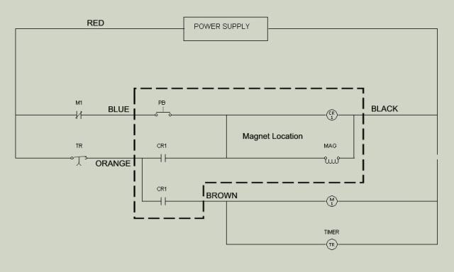
Here is the ladder diagram of my control system. Master Relay M1 and the Time Delay Relay are located at the power supply. The pushbutton and CR1 are located at the magnet location. Other magnet locations can be added by repeating the components inside the dashed box. To wire them in, simply connect the new components to the colored wires as shown. There will only be four wires total coming from the power supply/timer location. All magnet locations will connect to these same four wires.
A couple of digressions. Tony’s train exchange has offered DCC contolled couplers in the past if you are interested. The second digression is that the magnets in the magnetron tube of microwave oven are extremely powerful. If the polarity alligns correctly one may be able to counterbalance one and raise it for uncoupling when needed eliminating the electrical aspect completely.
These electromagnets can work, but a few items should be mentioned:
-
As has been noted numerous times elsewhere, the tiny Radio Shack pushbuttons will quickly burn out if used to directly energize these coils. These little buttons are rated for 0.5 A max. But they CAN be used to energize small relays with coils drawing less than this.
-
I just measured the resistance of a new Kadee 309 coil, not yet assembled into a complete electromagnet. On my new Fluke, it measures about 8.4 ohms. At 12vdc, this coil will draw about 1.4 A. Kadee talks about using 16 vac (RMS, no doubt, equivalent to dc in power), which would draw a little under 2 Amps. Self-wound coils would have to be checked to be sure.
The magnetic field depends partly on the number of ‘ampere-turns’ in the coil. Here’s the rub: the higher the number of turns (or smaller the wire), the higher the total coil resistance - hence lower current. Rolling your own takes some experimentation.
- The timer idea is a good one - I’ve built timers using 555 IC’s driving relays. They work. However, in the DCC environment, the 555 is simply not stable - no matter how well bypassed the separate dc power supply, and the 555 circuit board.
A timer is very desirable: surely someone operating as a guest will forget and ‘lean’ on the control buttons…
I’ve thought about using a heat-sensitive resistor - a kind of simple circuit breaker - but not followed up the idea.
So I’m very interested in the commercial timer mentioned above, and in its performance in the presence of all the noise and harmonics from nearby DCC wiring. Can that poster provide us with more information on the timer?
- Using coils of any kind can create an inductive kick at a switch, whether a pushbutton or relay contact. The time-honored method for suppression of sparks (and thus shorter lifetime of the contacts) is to connect a diode in the reverse direction (assuming dc, not ac) across the contacts to be protected. This mean
There is also a non-electrical alternative that works rather well. Hook up an under-the ties magnet so that it either slides horizontally or is hinged vertically. When not needed, the magnet is moved mechanically to the off position - hanging down from the hinge, or moved so the magnet centerline is close to one of the rails. When needed the magnet is pulled up or slid into position. Both are tried and true methods for magnets on the main line.
Another possibility - I haven’t tried on the mainline yet - are the 1/8" diameter cylindrical rare earth magnets. These are mounted in pairs, flush with the tie tops, either just outside or just inside the rails. The longitudinal range of a single pair of these magnets is pretty small - perhaps small enough not to affect a passing train on the main.
Of course, if there is no slack in the passing train, there is no uncoupling anyway. But that puts a premium on smooth running locomotives with excellent electrical pickup, level trackwork, and rolling resistance of cars being set right. Note that all these ingredients (plus couplers in good adjustment) are needed to make delayed magnetic uncoupling work well, anyway.
my thoughts, your choices
Fred W
Hi from Belgium,
I scratchbuild these uncoupler for my Nscale empire years ago from a small sketch published in MR.
You just need atube and plastic and of course insulated wire.
Take a look at this link and look the pictures.
They could be used whith the timer posted before it’s a nice idea; be careful they are pwerful but need a lot of current; they are placed under the track in a slot cut in the roadbed, I use a mall thin translucid plastic between the track and the uncoupler; they are glued whith a construction glue under the track.
Good luck.
Marc;
A few years ago, I spent alot of time coming up with a fool-proof method of electromagnetic uncoupling. I ended up using a 24 volt DC power supply, partly because I already had some from salvaged industrial electrical control panels. 24 volts seemed a bit much for a Kadee e-mag coil, so what I did was purchase the O-scale Kadee e-mags. These come with two coils. By wiring them in series on the 24 volts, each coil is getting 12 volts and the arrangement draws around 1.5 amps. I took some sheet steel and cut/bent extra sideplates to more strongly focus the magnetic field. I have no issues with uncoupling with these. The e-mag is plenty powerful to uncouple even when the Kadee couplers are not perfectly adjusted. The exact same thing could be accomplished using 12 volt DC power by connecting the two coils in parallel. All associated relays would need to be 12 volt DC coils.
As for the pushbuttons and relays, I am using industrial equipment, not any low-amperage stuff. The relays and pushbutton contacts are rated typically at 10 amps, so no issues with burning them up, even with the “kickback” from the collapsing field around the magnet coil. Also, no issues with any harmonics from the DCC or interference with the DCC.
DPDT relay - http://www.factorymation.com/s.nl/it.A/id.4446/.f