It’s funny how long you are familiar with something then all of a sudden the question hits you, “Why is that?”
The drivers on steam locomotives are “lopsided” witih mass:
I speculated why that was then observed a steam locomotive operating slowly to confirm my hypothesis. It appears that the heaviest portion of the drivers - all in the exact same alignment but NOT necessarily with identical mass (see photo above) - make contact with the tracks that corresponds to the forward movement of the piston. I’m surmising this is because it’s that particular movement of the steam cycle that creates the most stress on the drivers and where most of the tractive power is exerted to propel the locomotive forward; hence the need for mass. Otherwise, “proportional” drivers w/o mass would collaspe under the strain after a while. Am I correct?
I also viewed some Scullin disc drivers. Some types have a pronounced mass to them while others are more symmetrical in appearance; although - on a few of them - I can visualize hidden mass built into the drivers between the openings in the driver disc - e.g. the middle driver of the Dreyfuss Hudson below:
I imagine that there was/is some real engineering involved in [just] driver design [alone] to balance between weight and durability. You’d want to make the drivers as light as possible but still able to take the stress and the pound
The main reason for counterbalance was to offset the weight of the rods and linkages. Saving weight was not a consideration in design. Weight on drivers without going over the railroads bridge laws was most important. Was disc drivers stronger than spoked drivers? Possibly. Spoked drivers were around for more than a hundred years and most of the last revenue steamers were sporting spokes. Disc drivers seem to have been a design fad much like streamlined shrouding.
Piston thrust fore and aftalso called dynamic augment was not the detrimental cause of track failure. The use of jointed rail, light weight rail, deferred maintenance, and additional tonnage per mile was the major factor for track failure. The railroads were still failing years after deiselization.
It is a matter of attempting to use counterweights on the drivers to balance the greater weight (and differeing weights to boot) that the side rods, and valve gear connections, bring to one side of the driver opposite the counterweights. Likely speed is another factor, which adds a kinetic factor and complexity to issues of simple “static” balancing.
I can recall reading that as freight train speeds began to increase after WW 1, the hunking drag freight locomotives that were now being pushed closer to their theoretical speed limit (meaning speeds closer to their driver diameter versus the drag freight era’s speeds of about half the driver diameter) egan to do real damage to the track, so in turn the track got more robust and the roadbed deeper and eventually freight locomotives were designed with larger drivers to accomodate the faster speeds expected of them. I have also read that as power and speed increased that sometimes drivers would shatter - I assume that means the spokes – at the areas of greatest stress, and sometimes the side rods would also fail rather spectacularly (and rather dangerously for the occupants of the old centercabs on the CNJ and Reading etc.
You have likely seen the elaborate testing track that the Pennsy had for its steam locomotives where the locomotive alone would be run on rollers and the engineering types would study all the factors of efficiency and balance. I suspect the balance issues associated with faster speed and high tonnage were all part of the tests.
I assume there was good science behind all of this but clearly some locomotive builders got it bettter then others. The Milwaukee Road 4-4-2 and 4-6-4 pulling the Hiawatha trains were said to be almost certainly capable of a good 20 mph or more faster than the 100 mph they routinely ran at, ditto the Pennsy T1, and the Norfolk & Western J class had surprisingly small drivers for the speeds it accomplished, and it was said to be a smooth run
Hoo boy is there a lot more to this subject than described so far, with very different details in many respects.
Counterweighting the mass of rods as a practice is very old, but it is not usually possible to put the lateral center of mass of the counterweighting precisely in line with the lateral centerline of mass of the rods. Some interesting types of design, notably the ‘revised’ rod arrangement on some of the N&W Js including 611, reflect the relative importance of keeping the most mass as far onboard as possible.
Meanwhile, there is a problem with inertia vs. suspension – the axles must be able to slide vertically with as little cumulative wear or binding as possible, but should shift fire-and-aft in the pedestals as little as possible (this was the death of Porta’s fascinating attempt to support driver axles via a bar linkage, like some modern high-speed trains) Now on a quartered engine the momentum on one side is horizontal while on the other straight up and down. Consequences follow unless careful balancing is used.
The mains pose a special problem. The back part rotates, and so can be balanced with counterweights, but the front part is constrained to slide with the crosshead and can’t. This leads to the necessary-evil practice of overbalance to reduce the yaw and other effects of that unbalance, and overbalance inherently ruins carefully angled rotating balance. At least one aspect of reciprocating balance – surge – could be addressed with the Langer balancer (Westinghouse, 1947) but yaw on an engine with zero overbalance requires means like very stiff and well-damped lateral, and these of course raise their own problems. Ralph Johnson of Baldwin notes that the ‘best conventional wisdom’ is to find the center of oercussion of a main rod (he gives procedures) but he maddeningly says nothing about duplex practice (e.g. with long rigid wheelbase, a very massive tender, and high-speed guiding improvements) and abso
There was real engineering involved everywhere in steam locomotive design: drivers, springs, rods, roller bearings, just everywhere.
Looking back, those of us who have ever had even just one class in mechanical engineering (we civils are still required to take one mechanical engineering course, as there are some basic mechanical engineering facts that are on the Engineer-in-Training exam required to eventually sit for the Professional Engineers’ licensing exam) can be amazed at the amount of work done with just slide rules and tables that solved decimal equivalents. For pete’s sake, those guys did not even have a decent calculator, yet the mathematical precision of their computations and the plans from that era is simply outstanding. They were truly design artists and not merely mechanical engineers. To me that becomes clear when looking back at their body of work.
Then if you really want to be impressed, read William Kratville’s books on the UP 4-12-2’s. It got a whole lot more complex once you tried to deal with the counterbalancing effects of having a three-cylinder locomotive! Then you learn there is more than one approach to properly balancing said three cylinder locomotive, but that also involved its own set of issues.
Today we live in an era where our public schools actively teach that you don’t need to memorize mathematical facts and figures anymore, and my son, a high school graduate, is not able to do multiplication and long division like my generation could because they barely even taught it at all. Memorization of facts is deemed “unnecessary” because you can go get a calculator to do it for you. Some even say memorization is racist and privileged and “holds back” those who don’t memorize well. BS.
But what happens when the computer is down? How do you check engineering calculations done by your cadd
I get what you are saying. My statement about “real engineering” was solely focused on the drivers but not to imply that the designing the rest of the locomotive was a piece of cake. It’s fascinating to look at all the movement involved with a steam locomoitve and not be in awe that someone had to figure out that that “part” had to fit right there at that location and function in that manner to make the entire system work properly.
Yes, and it’s sad that certain rote memorization is looked down now by some of our teaching institutions. Just because someone doesn’t “memorize well” doesn’t mean it’s not worth doing; you just have to work at it harder…and that teaches persistance and perseverence. That’s how I learned.
And if you really want to befuddle someone, give a cashier extra change after they have totalled the cash register out for that sale. Some folks are unable to calculate in their head anything other than what the cash register display tells them. Truly sad.
I have had the privilege to talk to several old PRR guys who have ridden, fired, and engineered the I1sa. Yes rough riding. But not like you would expect. The unexpected side lurch was the most dangerous and toss you around in the cab. Wide stance and get ready to grab something. One fireman said his foot fell off the door pedal and the shovel got wedged and the handle broke. They all agreed the borrowed ATSF oil burners rode better. They all agreed if given a choice they would take the brute force of the I1sa over even the modern power of the J1 and M1. No other locomotive on the roster could pull 98 loads of ore off Whiskey island without doubling or helpers.
Higher speeds, heavier trains, more powerful locomotives, reduced maintenance cost (yes, track damage was a consideration here, too) all while trying to improve fuel efficiency and utility, or terminal time, of locomotives were all carefully, and exhaustively studied particularly in the “superpower” steam years.
Reducing mass was certainly a major consideration.
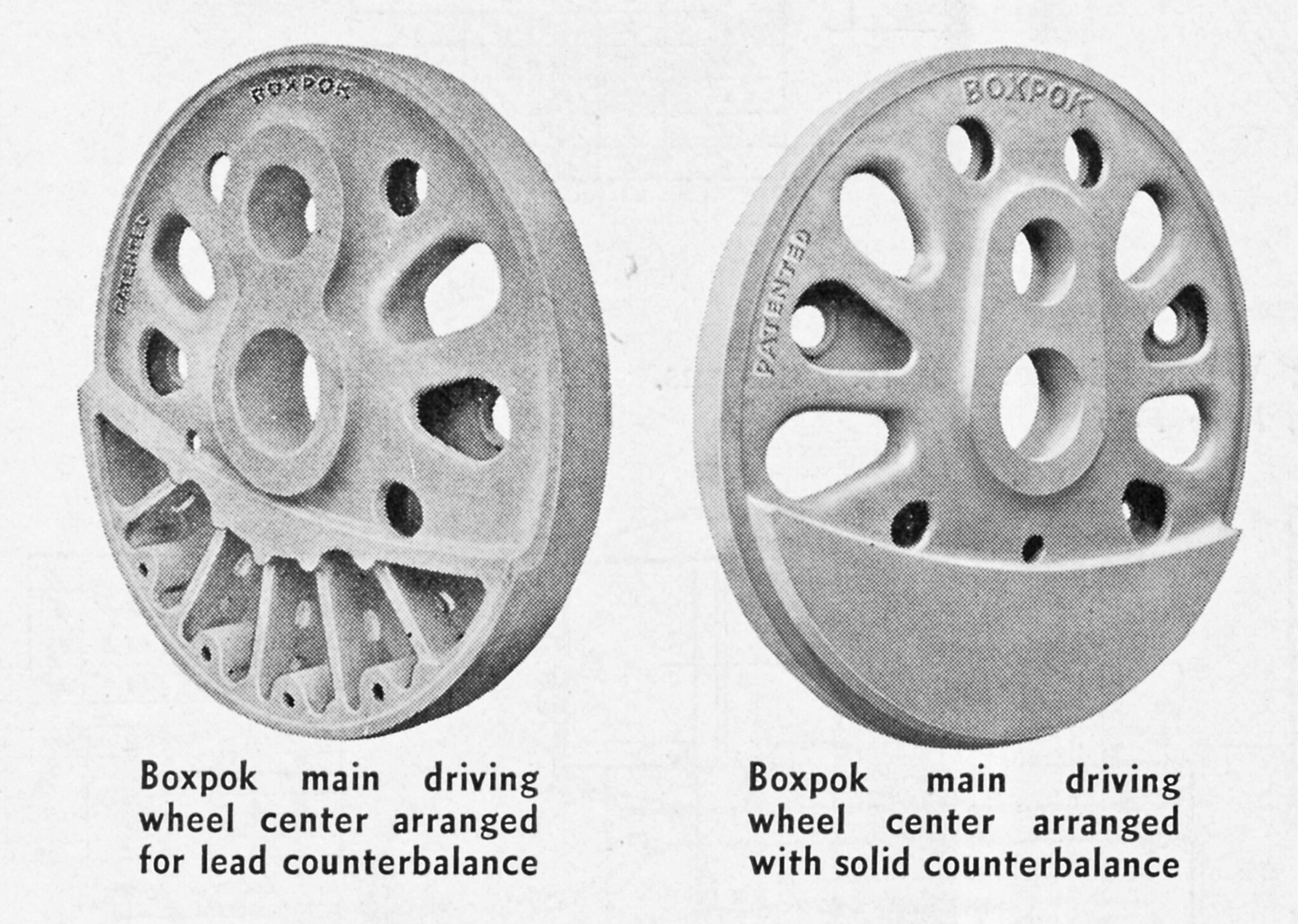
Note that one of these Boxpok designs shows that the counterweight cavity can be packed with lead for higher density weight at less volume. Like the Scullin Disc these drivers are cored to increase strength and reduce mass.
It’s actually much easier to balance a 3-cylinder DA – John, review your mech notes to look up ‘Swiss drive’. Interestingly this is true even if the center cylinder is nominally a out of 120-degree geometry for clearance. Inherently 3-cylinder engines get around the dead-center issues of 2-cylinder power that require quartered phasing, too.
What wasn’t easy on three-cylinder engines was design of the valve gear… or setting it properly! There was a story, too good to be apocryphal, about the SP three-barrels-of-fun engines that were like having an expensive mistress at every division point, that the shop forces had to keep a chronic lush on the staff because he was the only guy who could set valves well on them. The issues with Gresley on the Nines are well established, as was the Polish solution of a whole third set of outside gear on one side to cure the whip and travel issues later.
I suspect that the locomotive industry was an early adopter of Marchant and other mechanical ‘computers’ when developed. It is almost painful to consider the tedium involved in locomotive weight-balance calculations alone … and then doing it all over again each time some change in the auxiliaries or layout was made.
For fun, watch some of those videos where MIT grads are asked simple fundamental questions out of their discipline. I don’t really comprehend how that could be, but some very bright people have had that kind of hole in their tech understanding…
Nice job as usual, Ed. A couple of additional comments:
Most of the disc centers were in fact heavier than their spoke counterparts, even those that were weldments. This is analogous to composite vs. tube-and-fabric construction in sailplanes. The better balance-mass accommodation, rim bearing, lateral strength and freedom from fracture concerns made disc centers important in many applications, particularly as mains in low-mass retrofits – yes, T&P 610 has a Baldwin Disc main hiding in there, something you can win money in bars for knowing.
Interestingly, one of the fastest locomotives actually tested in America never had disc drivers, coupled or main, despite having nearly the highest starting TE of all 4-8-4s. And development of a solution to rim distortion and fracture, in the form of the Web-Spoke, was good enough to substitute for cast in many applications, including ‘interchangeably’ with both Scullin and Boxpok (pronounced just as they are made, ’ box spoke’) on NYC Hudsons.
The aluminum deserves further discussion, particularly because one of the test engines was a PRR I1. Ed will have the test picture with the rods bristling with strain gages. Aluminum is of course unsuited as a material for reciprocating-locomotive rods because of the stresses (the pins don’t see reversing but the webs do) and the things that make duraluminum alloys stronger generally do it by keying glide planes, metallurgy that progressively fails in ‘creep’ with a colossal predisposition to initiate stress raisers. This also, alas!, disqualifies it from being a lightweight composite driver-center material for tunnel-cranked axles.
What Timken was reduced to doing was using a much smaller amount of relatively heavy &#
It is … but this is a combination of evil overbalance and grossly inadequate lateral guiding, nor anything implicit in the apparent hippo-ness. Remember that the I1s were designed with 50% limited cutoff and slot ports to make them 50mph engines, and that English engines of the same wheel arrangement and relatively slight change in detail balancing achieved speeds of over 90mph.
What might have helped the I1 is the same approach the Germans and I think the Japanese used, and which in modified form was to be used on the British 5AT. To maximize adhesion, most of the engine weight is balanced over the coupled wheelbase, with an absolute minimum of additional bearing axles. (This formula is seen in the longevity of the N&W 2-8-8-2 layout and detail design, too). The ‘catch’ is that there is nothing to control lateral motion of the back of the chassis, and therefore any yaw or coupled yaw forces that lead to lateral acceleration back there. The solution is to provide guide wherls with no adhesive weight on them that can provide prigressive steering comparable to that from a Delta truck, and this can be done by revising the connection between engine and tender and pushing the lead tender truck up as far as it can go, actually well under the rear of the locomotive chassis itself…
Many of which were either nipped in the bid for other reasons, or designed out by liars and relative design morons.
Symentrical wheel arrangements like 2-6-2 and 2-10-2 with the main rod connected to the middle driver were notorious for “hunting” (yawing) back and forth. That’s one reason 4-6-2’s replaced Prairies.
There’s a little more to it. The problem is related to polar moment of inertia and the locomotive’s ability to counteract the transverse ‘turning back and forth’ yaw moment from the alternating quartered piston thrusts far from locomotive centerline. On the types concerned that thrust is applied nearly at the longitudinal center of rotation, so resonance can easily build up, but primitive two-wheel trucks cannot damp this effectively, particularly at critical speeds. Flange force from extended driver wheelbase is equal and opposite in yaw, too.
Note that a typical Hudson has this problem, too, and if the lead and trailing trucks are not carefully designed, and good leading driver lateral-motion devices are not provided,you can have the wrong sort of fun at entirely wrong times…
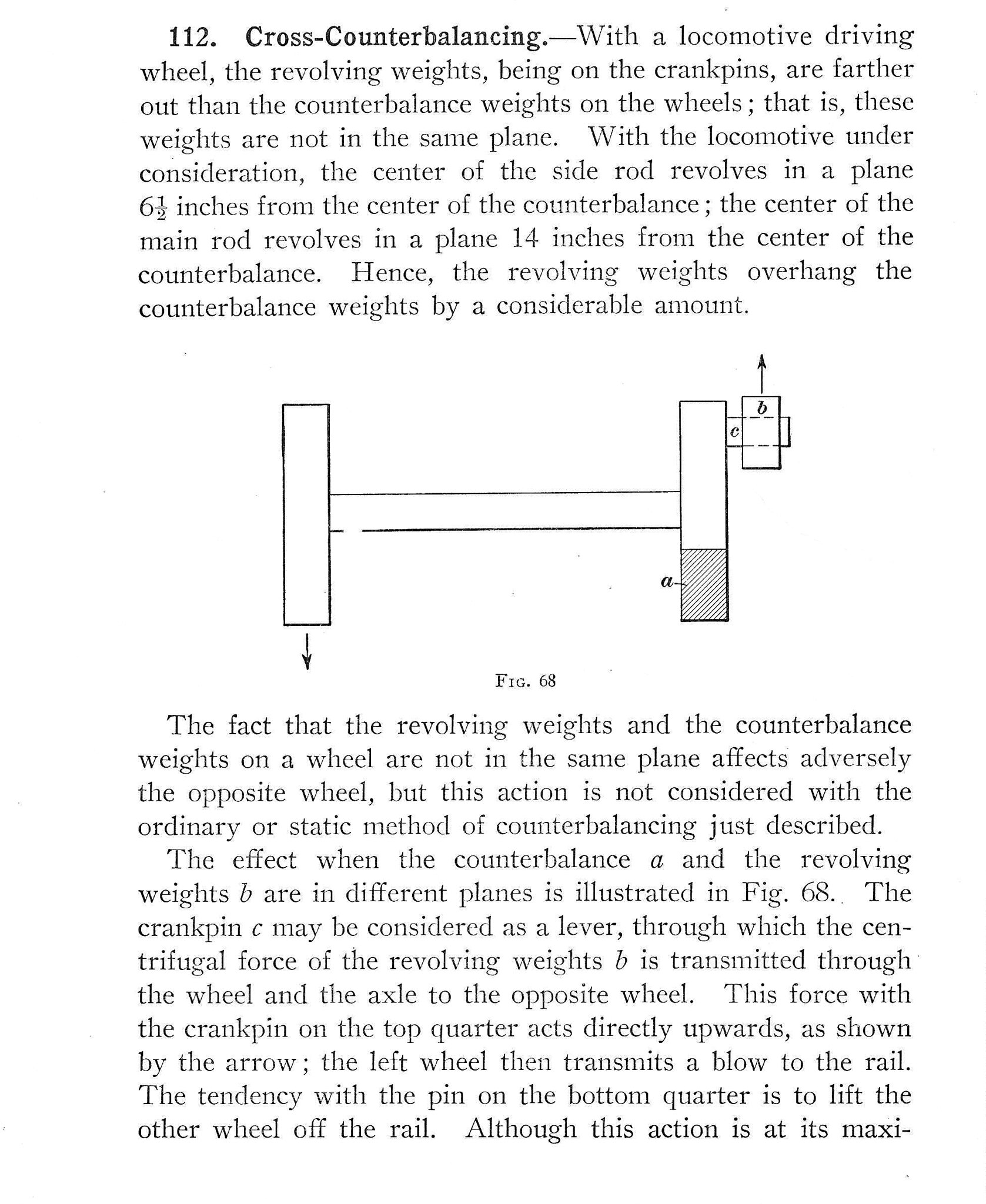
Thank you guys for the counterbalance illustration above. It’s very helpful.
Kratville said that in actual practice the maintenance of a 4-12-2 was the killer. Especially late in steam, the shop forces just did not bother to take the time to properly lubricate the 3rd cylinder–that it was most troublesome to get to and most helpful if the mechanic was a small and wiry type that didn’t mind getting dirty. So too many times they were just sent out without proper servicing…
Most extant sound recordings are of 4-12-2 engines badly “out of time”…due to the lack of thorough servicing and of course people who actually bothered to set the valves correctly.
A substantial part of the problem with the Nines was that, as built, they had that Gresley conjugated valve gear that Americans love to hate (it figures large in accounts of Mallard’s speed-record big-end troubles) and suffered enough from progressive lost motion problems and with having the inside valve being driven the other way that we come to see the extreme solution of three sets of outside valve gear substituting for the simple, light, and space-effective placement of levers on the pilot deck…
An interesting question that comes up from time to time is whether the Multirol needle bearings so successful in N&W practice, or the more modern offset bronze-caged modern rolling-element equivalents, could solve the problem Gresley encountered with using hard or roller bearings in oscillating rather than rotating joints. That might have gone a long way towards eliminating the slop, if not the offset in the timing that is often immediately characteristic of simple three-cylinder engines with Gresley gear…
These were a panacea for the ills of high-speed yawing especially on 39 foot jointed rail. In addition there were devices that automatically kept the driving box wedges “snug”. Hand adjusted brass wedges would get sloppy (out of tram) over time and this would add additional stresses (and lots of clanking) to the side rod bearings.
There was some discussion of this “mishap” at Classic Trains. Unfortunately, many of the photos have vaporized into the nether regions.
If you want to have fun, look up, and count, the number of individual devices on a PRR Q2.
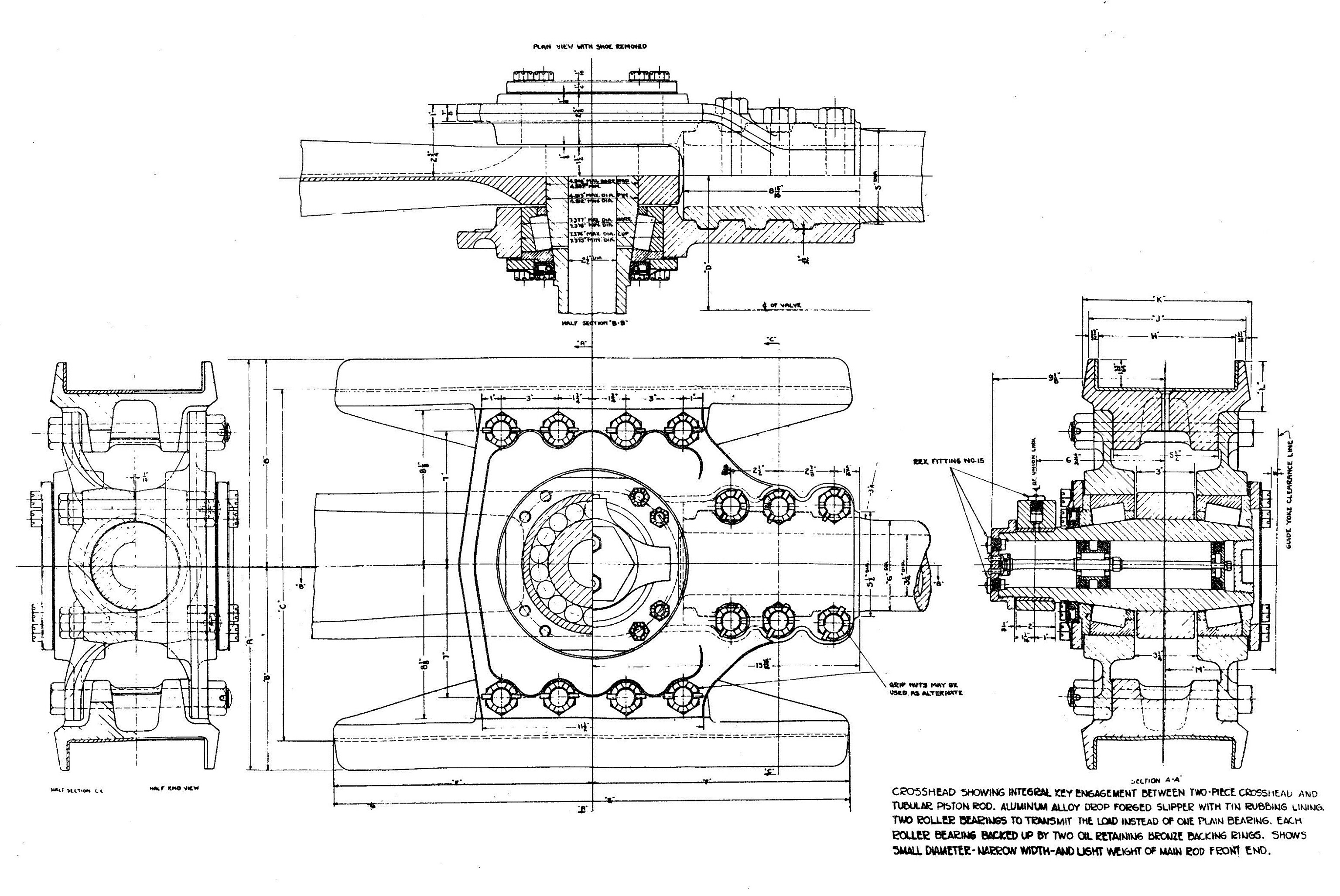
If you look carefully at a couple of Ed’s pictures (cf. his 8.214), you can see the combination of late roller-bearing ‘cannon boxes’ (where the two roller bearings are joined rigidly by a strong, usually tubular housing – the whole thing then floating laterally in the pedestals as controlled by lateral-motion devices ‘ahead and astern’…) If arguments about the excess unsprung mass of typical cast disc centers did not convince you, the irremediable unsprung mass in these arrangements will: there are colossal problems at very high speed between the inertial mass of drivers and the springing/snubbing arrangements that will fit in the equalizing…
The evolved practice at Timken in the years between the “100mph brochure” Ed provided (from 1936) and the practice on the Niagaras or the last N&W As is fascinating to study. I have my doubts, right along with Chapelon, on exactly how safe these things were at an actual 120mph and 40-percent cutoff. It’s a bit like the published Amtrak research on Acelas traversing the Metro-North-owned portion of the Corridor where regular shocks of 189g were recorded [:O] (no, that is not a typo; no, that is not an artifact of measurement; yes, it’s been confirmed from authoritative sources.) Bronze rod eyes will not help your pins much in those circumstances… [:-^]