I’m getting ready to lay the track for my new HO layout which will be DCC controlled. The power bus will be 14AWG with 20 AWG feeders soldered to the rails every 30-42" +/-. I was planning on using a series of terminal barrier strips to connect the feeders to the power bus but after doing more reading, I am now wondering if 3M suitcase connectors will be a better choice from the perspective of the electrical connection, cost is not a factor in this decision. Does anyone have any bias one way or another?
I certainly do. I use barrier strips, as you’re thinking of doing.
I will NOT use suitcase connectors on my layout. The blade that bites into the conductor is a different material, setting up an immediate potential for galvanic corrosion at the bite. The bite also creates a notch in the conductor which acts as a stress riser and fatigue point in the wire, meaning the wire can easily break at the blade with relatively few movements of the connector.
Then again, a whole lotta people use them and have experienced no trouble at all.
I’m sure you’ll get all sorts of pro-suitcase replies. So maybe I’m just paranoid. Funny thing, though - some of the folks who don’t mind “rolling the dice” with suitcase connectors that may fail ten years down the road will at the same time attach a set of feeders to every single track section on their layouts, fearing that if they don’t they’ll have track conductivity problems in the future. Seems a bit of inconsisitent logic there, but what do I know?
The IDC connectors will work for a while but in an environment where moisture and humidity is high (basements – garages) they begin to cause problems.
We used them on our club Lionel display (located in an old basement) and had the trackwork up for almost 10 years. We had use #12 stranded buss wires and #12 drop wires. The track we used was Gargraves and most of the #12 drop wires were soldered to the rails. The IDC connectors were used to connect the drops to the buss wires. We had the proper Scotckloc connector for #12 wire and they worked well for 5 years.
We then began to notice that the trains would slow down on certain sections of track and were not sure why. An inspection of the wiring showed nothing wrong and in the process of checking the wiring the problems seemed to go away. While this was OK it did not really explain why the problems even showed up.
Then a different section of track began giving problems. We had the layout set up blocks using industrial toggle switches and it was designed to be able to have 2 different transformers available to run any given section of track. So the transformers were not the problem as either one would not make the track run any better. It got so bad at the last we had to have the bad sections set on the other transformer set to a higher voltage just to keep the trains moving at the same speed section to section.
Then on the forums someone stated that the potential problems existed where the metal blades came in contact with the wire and very minute amounts of corrosion would form on the IDCs. This then explained why when we did our wiring inspections we seemed to correct the power loss but had not actually done anything except moving the wires around. By moving the wires we must have made good contact again by somehow breaking through the corrosion. I really could not see any of this in any of the connectors but then it probably was that very small amount.
We subsequently rebuilt the Lionel display
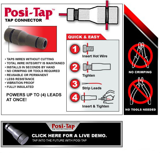
We are living in a parallel universe, as I am exactly at this stage as well. And I too am using 14g with 20g feeders! However, I will use the Posi-Tap connectors rather than soldering or using the 3M 567 Suitcase connectors.
Keep in mind that this is a heated subject and everyone has an opinion. You’ll hear everything ranging from the purist’s point of view that soldering is the only and best solution. Personally, I have using the Posi-Taps (you can get them at Wal-Mart) successfully and they make life real easy and the job goes quick.
My OPINION is that any of these methods is acceptable, but this is very true in all cases:
I will also agree that in a high humidity environment the IDCs could be problematic, though there are IDCs all over that seem to work for a long, long time in computers, phone and ethernet cables, etc. But I think they are copper on copper, where the ScotchLoks may not be (I haven’t researched this, so I can’t say for sure).
In any case, careful and proper installation is very important, whether it’s IDC, PosiTap, terminal strip, or soldering.
Unsurprisingly, everyone has their favorite. I used terminal strips on my last (first) layout and will probably continue the practice with this one, familiarity breeds a comfort level. Being a bit on the solder-challenged side, the best amount of soldering is the least amount of soldering. And, I must say, that high humidity is not a big issue here in Phoenix.
I, personally, use terminal blocks (several rows of studs with nuts top and bottom and washers between wires,) and have been very satisfied with their electrical performance.
One additional plus - it is very easy to label every terminal! IMHO, this is the key to successful troubleshooting, when, as and if required. Murphy will assure you that the unlabeled connections are the ones that will go sour first!
Just my [2c]. Feel free to disagree.
Chuck (modeling Central Japan in September, 1964 - with LOTS of terminal blocks along the aisleways)
Terminal blocks with jumper strips and I will be good to go.
Either way, consider making a what I call a scooter chair. Mine has a
frame of 2 X 2 and 1 X 2 wood, for everything else. I used sheet rock screws and
1/4-20 bolts to fasten everything together. The back rest is in a sloping
position.
Make it adjustable. I have swivel casters of about 1 1/2" OD.
I made one for the local club also. Just about everything is scrap wood
I picked up. It sure helps to scoot around under the layout.

rich
I have carpeting under my benchwork and it is a little lower than most would prefer so a scooter pobably would not work. But, it’s a great idea.
I’m soldering all mine. I’ve had bad luck with connectors in the past.
Would you be kind and post any pic. or a drawing if possable? Thanks Terry
It is easier to post them to another group and give you the link.
http://www.2guyz.info/Forums/viewtopic/t=3449.html
rich
I solder all my feeder wires using a good pair of wire strippers which will separate the insulation in the middle of a wire, wind the feeder wire around the bus, hit with the solder, and finish off with liquid insulation. I solder as many as possible at the same time and it goes pretty fast. I use terminal strips for all other things which I may want to move later…turnout wires, signals, panel wires, etc.
Good luck and have fun. Hal
Hi bearman
I use a combination of terminal blocks and soldered connections and very rarely have I had problems.
I am assuming the suit case connectors are the little boxy things you snap shut over the wire that Auto electricians love.
In my books they are a you could not pay me enough to use them job I found them very unreliable in long term use having read this thread I now know why and will not ever use them for anything other than a quick short term temporary wiring job.
regards john
Your assumption is correct re: the suitcase connectors. I have pretty much settled on my original plan of terminal strips and solder.