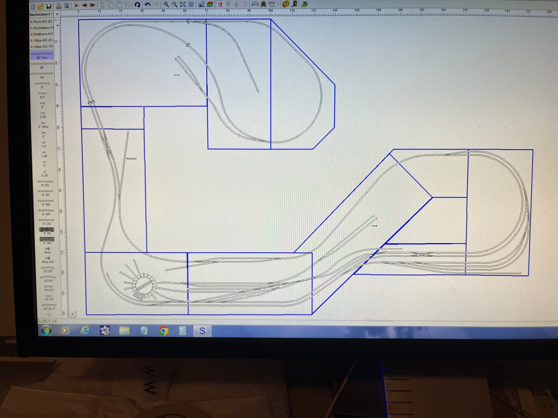
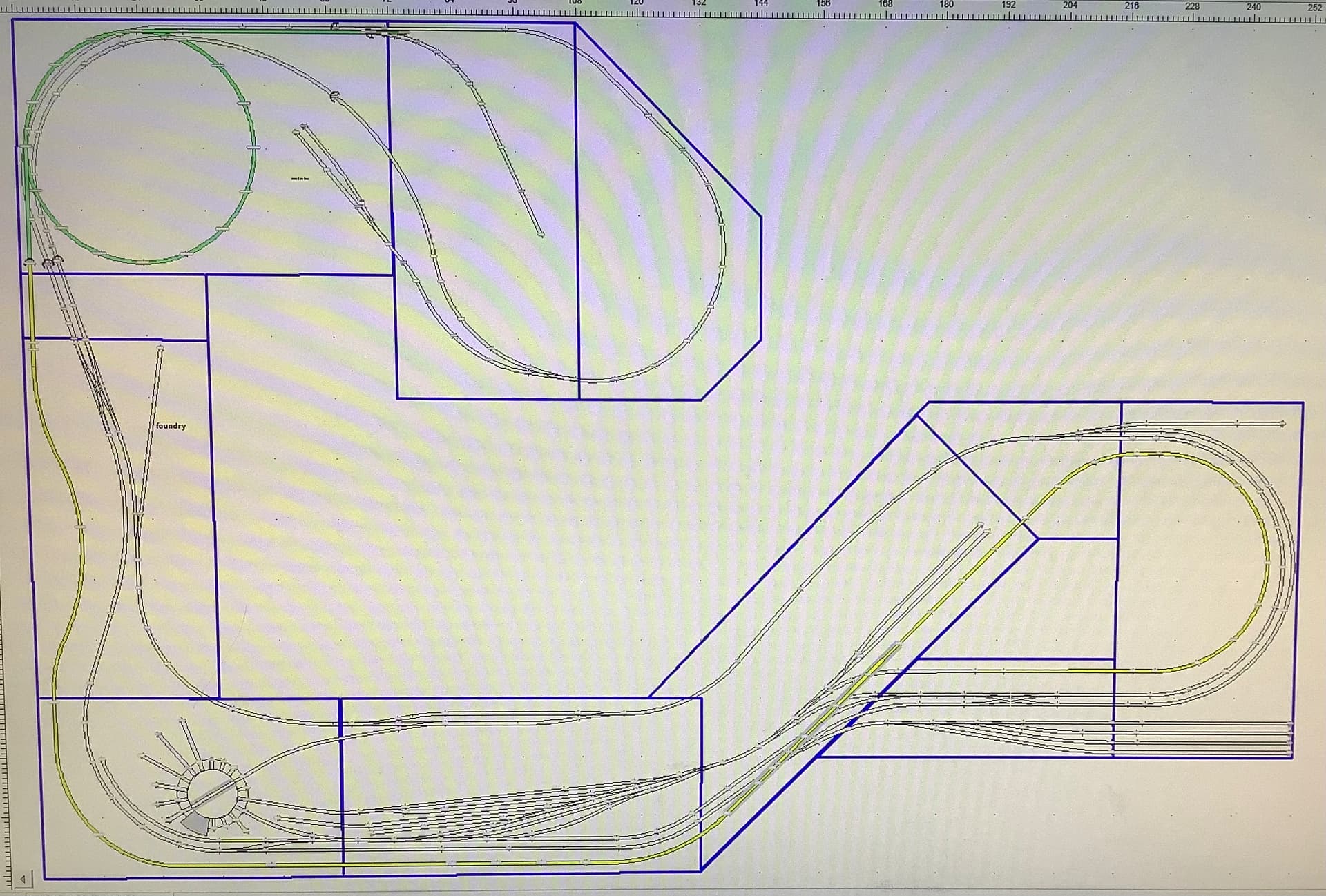
I am starting a new layout and as per the bosses (my wife) instructions i have designed it mostly in modules of 3x6 feet that can be (but probably never will be) disassembled. Her thoughts being it needs to be completely free standing from the walls and possibly moved when i guess we die. (You know once i get this sucker built i aint going anywhere lol….).
Anyways i have done up track plans that i now find out i need to modify slightly as peco doesn’t make a #5 switch in the unifrog design. But i have tried my best to run as many joints as possible straight across the joints between modules. But i have many that are not.
I have this idea to get a bunch of code 83 2” pieces of straight non flex atlas track (since i cant find any straight peco track) and build them into the layout at every potential splice between modules then if one day i ever do for some reason need to disassemble the layout i would cut them with say a Dremel cut off wheel.
Any ideas from you experienced folks would be much appreciated
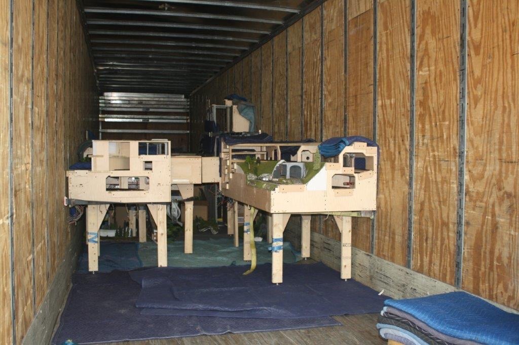
I can share how a professional layout builder constructs a layout in modules. The modules are sized ultimately by weight but almost always accessibility from the street to the layout room sets the maximum module size. My layout was built in their factory in Miami, tested, disassembled, shipped to SoCal, then reassembled in my layout room.
The layout could be disassembled and moved and this builder has done that in the past. All the track joints are at the module boundaries, there are no short drop in pieces. On final assembly the rail joiners are soldered. Pieces of tie strip are sometimes slid in at that time, sometimes it was not necessary. There were a couple of places where a turnout sat across a module boundary, they were just removed for shipping. Moving the layout would require cutting through the soldered track joints.
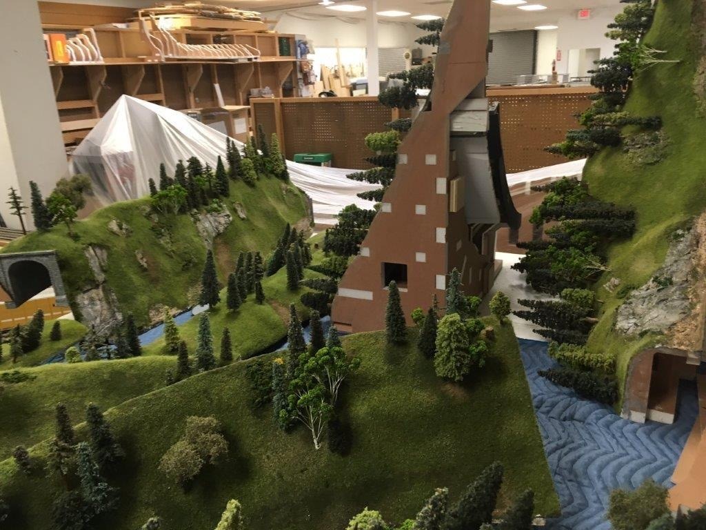
The scenery also has to be jointed at the module boundaries. Much of my layout scenery simply lifts out.
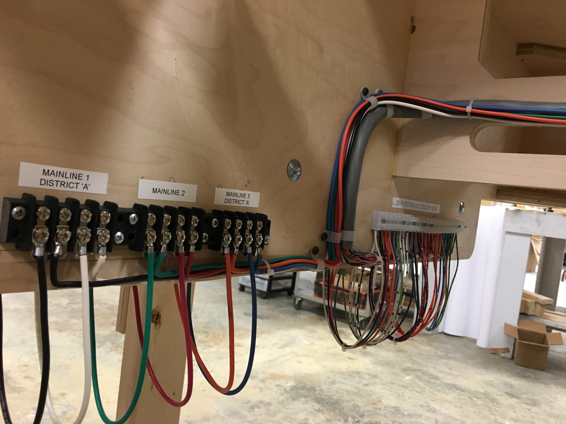
Do not forget about the wiring. No wires cross a module joint. All wires land on terminal strips at the module ends. Jumper wires connect the terminal strip pairs.
The layout sits on braced legs. The layout is anchored to the house floor and walls only at the entry swing gate. There can be no movement or flex if the gate is to work properly for decades.
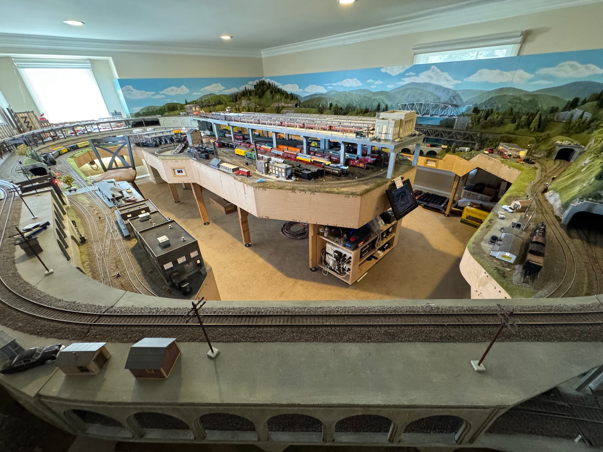
Here are a couple of pictures. First during factory testing, in the shipping van, some of the removable scenery.
Thanks Tom that really looks like a fun layout to operate and has a lot of depth and variety to it. Everything looks top notch.
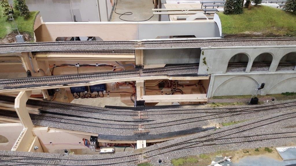
So i see from that picture where you zoomed in on the tracks there is one where a curve enters a turnout. Would that be flex track on one side of the joint or is it a peice of ridge track.
My concern is running flex track across the joints between modules. My idea is not to have removable short sections between them but have the ends of the flex track fixed to a short peice of straight track that would prevent the kind of involuntary straightening that occurs in joints of flex track because the rails are not completely rigid in their connection to the ties.
99% of the track is flex. The only track not flex are the uncouplers which are not in those pictures. Even the turnouts (#5, #6 and #8) were hand laid using rail stripped from the flex track pieces. I will find some relevant pictures and post them.
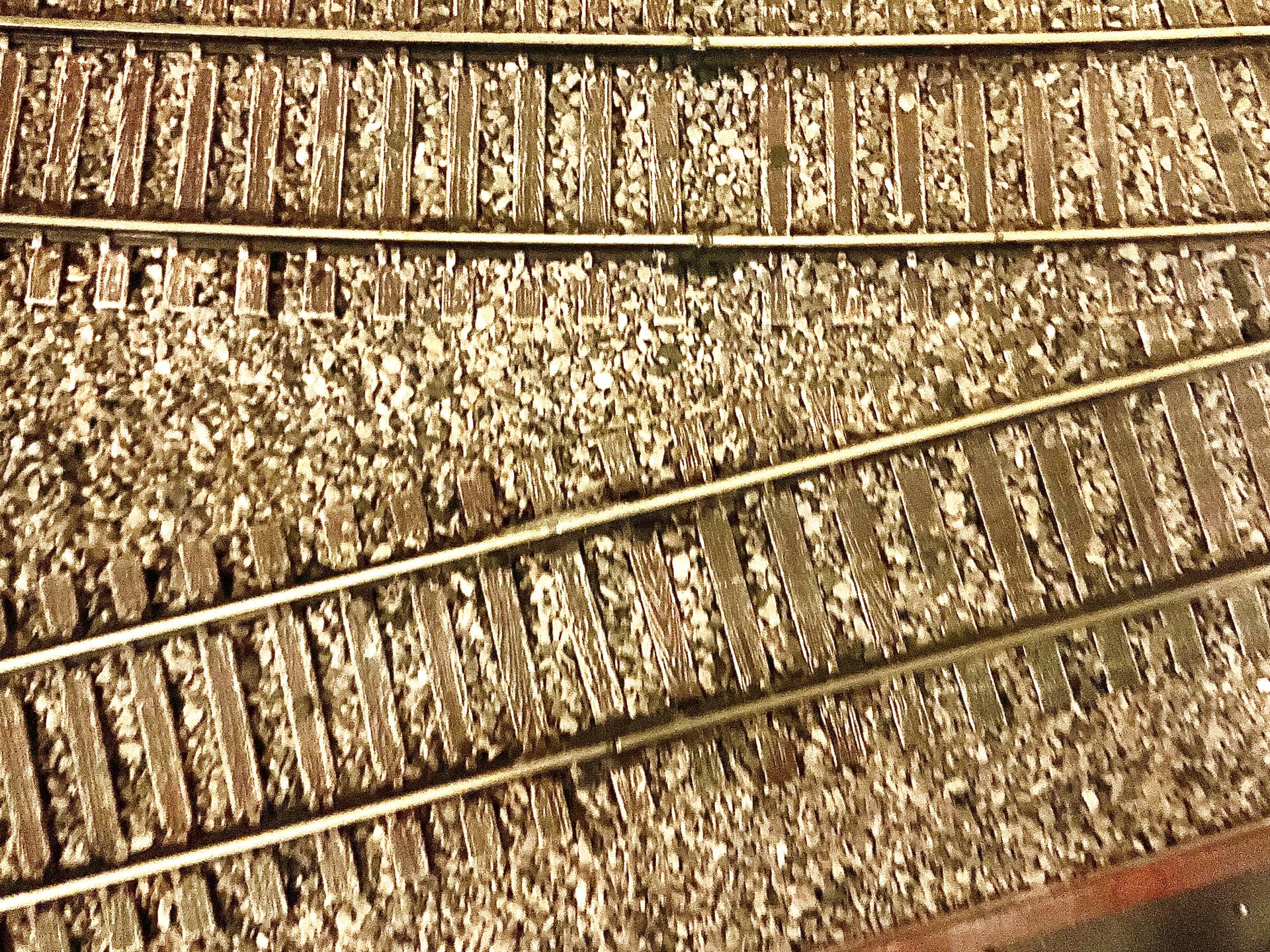
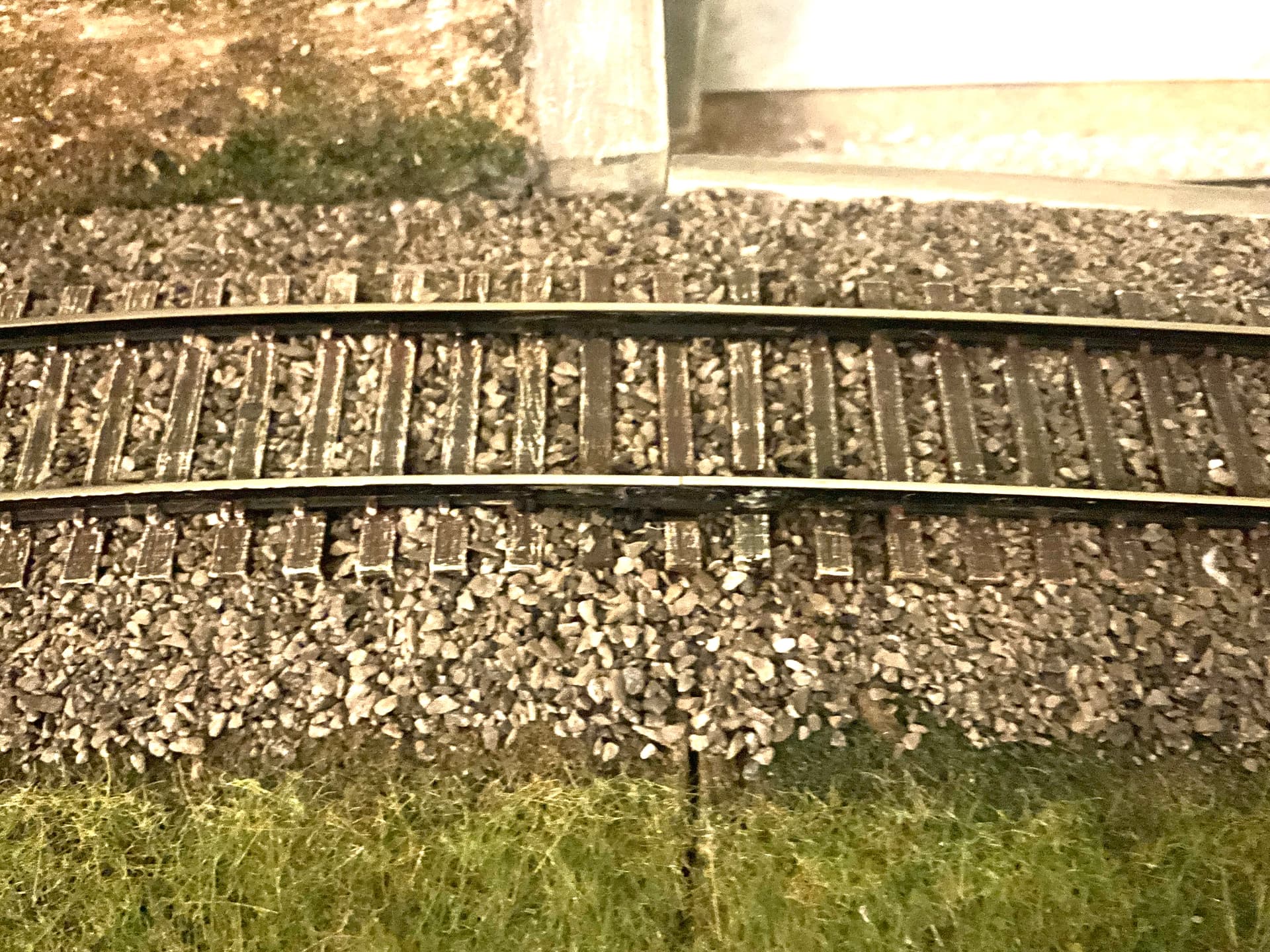
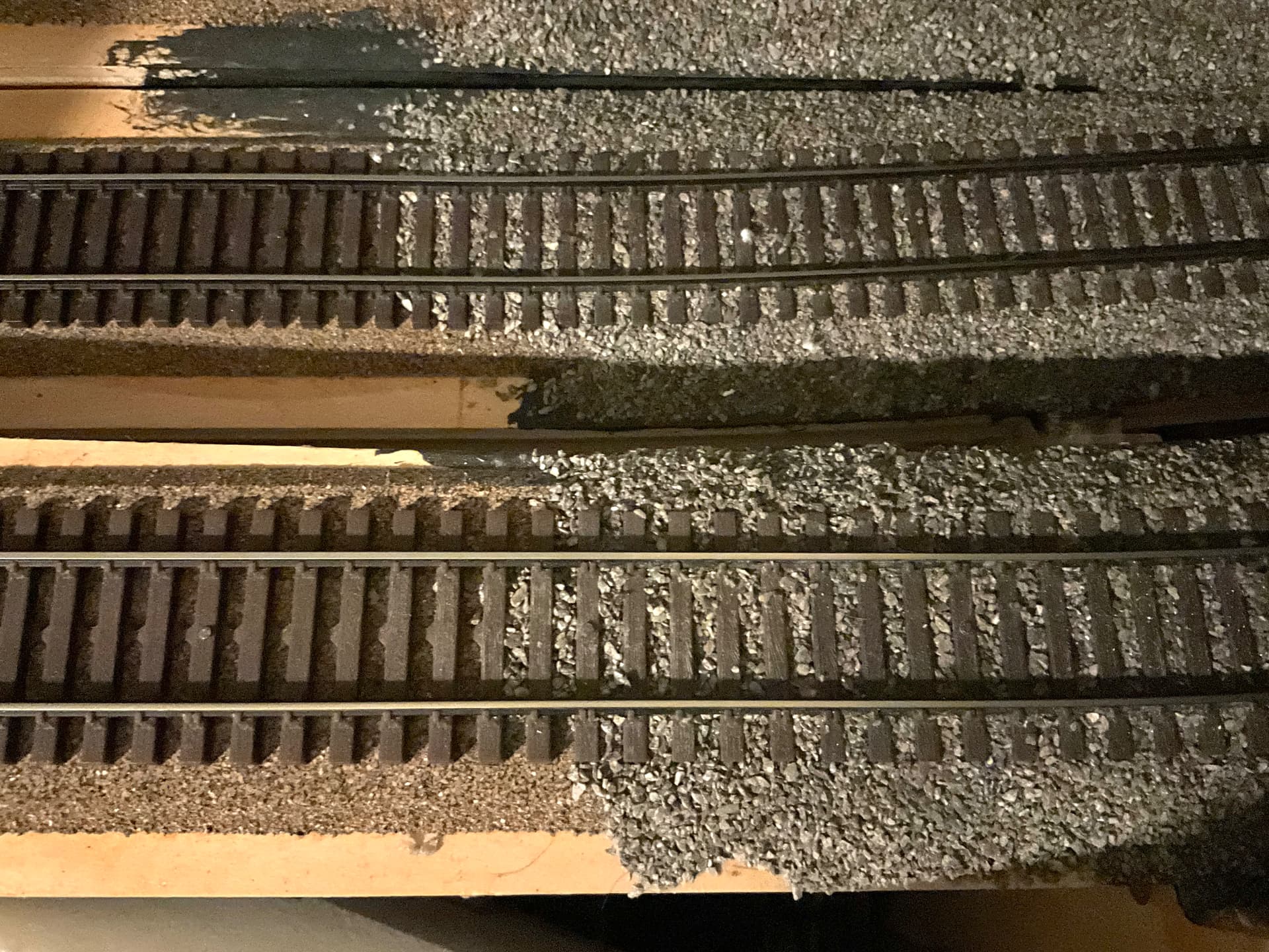
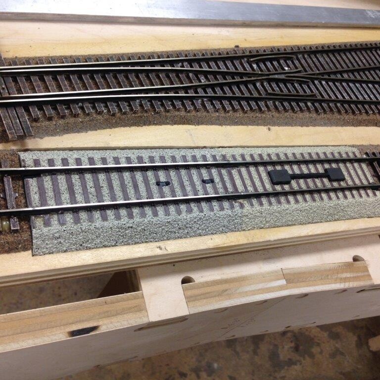
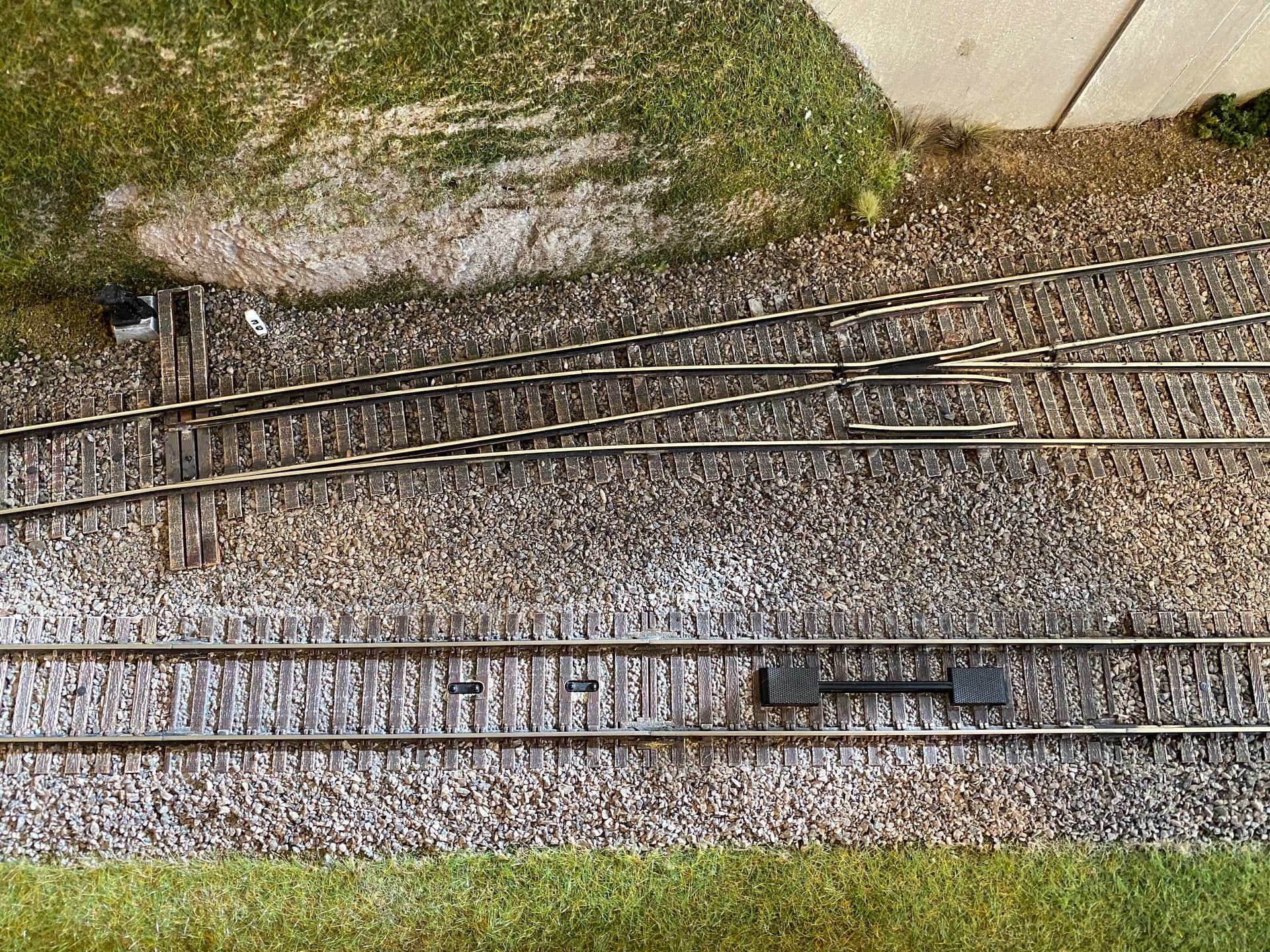
Here are some pictures I just took that may help. The first picture shows shows a curve flex track ending at the divergent leg of a #6 turnout. Track on the top, the nail is in the 5th tie to the left of the joint, the turnout nail is in the first tie. The next picture shows a curve crossing a module joint. The nail is in the sixth tie to the left of the module joint. The next picture shows some hidden unballasted track meeting ballasted track near a module joint. The ballast helps hold the track in place.
The final two pictures show two 5” pieces of sectional track (Sensor Track on the left, uncoupler on the right) before and after ballasting.These short pieces are always in strait segments of track.
I went to Miami five times during layout construction, laying the track at the module joints looked really easy, but these were professionals who had built close to 100 layouts. The flex track we used really wanted to be straight, it did not like to be curved.
Thanks so much Tom these pictures and your advice have been most helpful. I guess i should not be so concerned with the matter. My wife accuses me often of over thinking things to death. But you’re right I should just go about getting on with things. Attaching the track with spikes close to the joints and the ballast will take care of things your right.
You must be very pleased with your layout the great level of care and detail the builder’s exhibited is extraordinary. Some of the joints are so well done i cant see the joints in the rails just on the table in the background.
Kim, your track plan looks interesting. There is an advantage of having a single level track plan, it makes laying the track much easier. My layout has 4 distinct levels plus a lot of hidden grades between the levels, makes it much harder to work on. The builder I used has done some display layouts that are assembled and dis-assembled seasonally. These use the short, drop in pieces of track at the module joints because the track cannot be soldered on those layouts. The track plan is also much simpler.
One other method they used on my layout was to put offsets in a couple the module joints to accommodate the track plan. This was mostly in the freight yard area where there are a lot of turnouts. Hopefully your layout will be easier than you think to lay the track at the module joints.
Thanks i hope it goes smoothly too across those seams. There is some grade changes in my plan I turned those layers off to show all the joints better in my original post so folks could get an idea of the amount and complexity of them all. I did end up redoing a small bit of it replacing all the #5 turnouts in the yard with #6 as there the only ones available in the unifrog design turnouts i decided to go with.
There is not really any planning yet on the upper deck as i know i need to knock out this first level if i ever want to get to level 2. My wife really wants to have a closed loop to see trains running round and round without any real operating. And a space that we can utilize all of the models and structures we helped her dad with and have now inherited. They are basically transition era buildings, rolling stock and locomotives.
Myself i am more interested in modelling a short line built around 1895 in the silvery Slocan area of BC. And part of James Hill’s Great Northern empire at the time. Kaslo & Slocan Rwy. I have that spur starting off climbing off the table slightly on the inside of the loop on the lower right then crossing over the yard and up the wall around to the upper left corner of the plan where there is the helix.
I have a couple great books on the history of the area and many pictures of things like mines, stamp mills and overhead loading hoppers from the mines that it served sometimes several hundred feet above the line via gondola hopper buckets or trolly cars. Im sure it will provide many years of scratch building opportunity.
Looks like you will be doing layout building for some time to finish the complete plan.
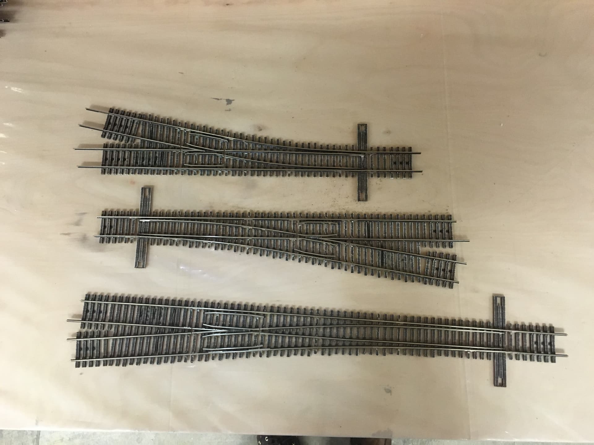
All of my turnouts were custom built using Fast Track jigs. What we needed were not commercially available. All the frogs are powered, I find that is essential, at least for the #6 and #8 turnouts. I did not test a #5 but I suspect some of the engines could stall when switching on the yard ladder. We used the #5’s in the freight yards. Below is a picture of the three numbered turnouts, #5, top, #8 bottom obviously. Laid out in CAD, the #5’s in the single ended freight yard added one additional 40’ car to the siding capacity.
After 9 years of operating my layout, and continually exercising no self control of engine and rolling stock additions, I find my on-layout engine parking is inadequate. Not directly related, I would have compromised my minimum radius to add a third track in the hidden staging yard. I had no idea how useful it would be.
Yes i can imagine parking does become a problem for sure. I lost a lot by switching to the #6 turnouts. Initially i had a few pull thru staging lanes planned but came to realize i had space for longer trains if i just one ended that portion. But left the possibility to add that feature where i currently have my workbench located on the right side of the plan. We will see if it comes to that.
Kim, I was in a modular club and the joints were a constant battle. Our solution was to use 6" straight pieces of Atlas track between modules. The ‘longer’ joiner tracks make a smoother transition over the joint. I ballasted my joiner tracks by affixing clear shipping tape to the back of the joiner track ties, cutting away the excess but leaving 1/4-3/8" extra around the perimeter, then ballasting as usual. I had lift out ballasted joiner tracks. Not perfect but looked better than no ballast.
I’ve been around modular model railroading for the past 12 years. Most modular standards started out with “fitter” pieces of straight track. This allowed for limited misalignment when the modules were assembled. But putting fitter tracks in was a huge time sink in setting up large modular layouts for a weekend. And generally look terrible. And new fitter sections had to be cut each setup because one person’s inset didn’t match another’s.
European Fre-mo, NC S&SS, and other individuals realized that if you have a method of quickly but very accurately aligning the modules with each other, you can run rails to the edge of the module. Rails have to be in “permanent” alignment with the end plate, and the end plate alignment method has to maintain alignment in all 3 dimensions. Pins (S&SS uses tapered 1" tube) into sockets are typically used. Pin position is based on a shared metal template so that all modules match. At the module end, the rail is typically soldered to either brass screws or a securely mounted printed circuit board. Rail alignment on clamping the modules together is thus assured.
If you are never taking your modules apart, or are only taking them apart once, this is overkill. And if your modules are really sections and will never change positions relative to the other sections, you don’t need each end plate to be the same.
My recommendation would be build your sections, bolt them together, and lay the track across the joint. Solder the rail to brass wood screws on either side of the joint, and only cut the rails when you are going to take the layout apart. Adjustable legs on each section will help with realignment when you go to rejoin the sections after a move.
Avoiding turnouts across section joints is the easiest way, but may compromise your track plan. Since you are always keeping the same sections in the same relationship, there is no need to use identical length sections. Move the joint to avoid the turnout, not the turnout to avoid the joint. Or if you can’t avoid a turnout over the joint, use the turnout as your “fitter” piece of track. Solder the rails the turnout will attach to wood screws half a rail joiner back from the end, and this should give you pretty good alignment on re-assembly.
just my experiences
Fred W …modeling foggy coastal Oregon in HO and HOn3, where it’s always 1900…
Thats a good tip on the spacer and neat idea on the ballasting.
That sounds like not only solid advice but also a solid less problematic joint if like you say. And I think as well probably won’t have to worry about taking apart and reassembling.