I do all my track soldering with a cheap-o Weller iron I picked up at the home center. Considering this option has worked for me for around 40 years, I see no reason to invest in resistance soldering equipment for working on track.
A few more thoughts:
Soldering is an essential skill for model railroading. Read up and practice.
I solder ALL rail joiners on curves to maintain alignment. Relying solely on the joiner will guarantee a kink in the rail eventually, assuming it doesn’t happen from the start. I solder nearly every other joiner to keep the track lined up too (I only have a few joints on straight track that are not soldered).
There is absolutely no need to solder the joiner prior to installing the track on a curve. It’s easy to hold the rail in place with something like a file or other flat metal object while soldering, and keep it aligned until the solder cools.
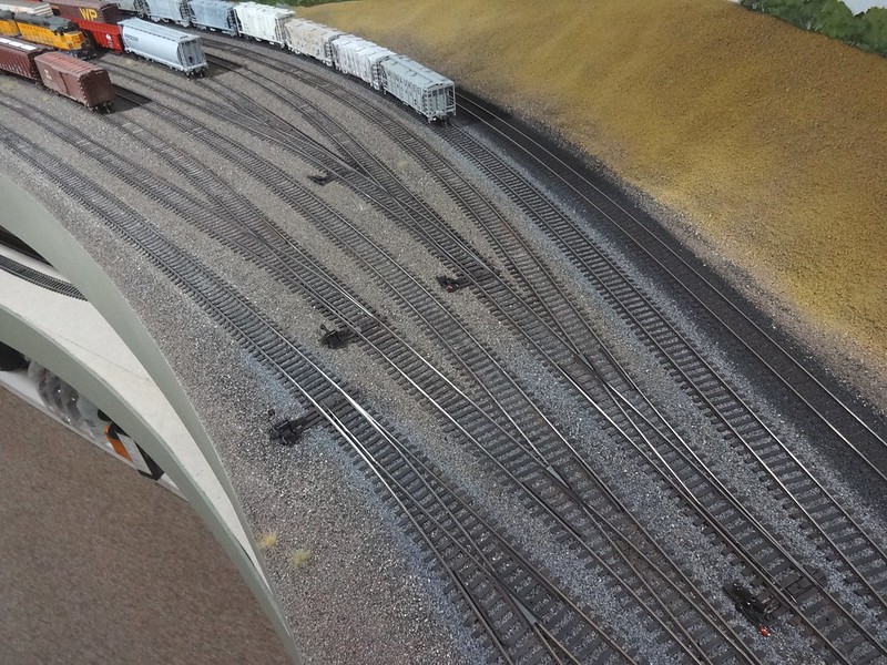
As shown above, soldered rail joints on curves can conform precisely to the flow of the trackwork. Rather than attempting to carve plastic ties for use under the solder joints, I use wood ties (often cut from something like 6X8 scale lumber), which disappear once the track is painted, and have the added bonus that they don’t melt if you solder close to them.
I’m saddened to hear that. I saw that post early on, when people were mentioning he’d been quiet for a while, but I figured he was on a cruise or something. I missed the news. Seems like a lot of folks here really appreciated him.
Thanks for all the continued feedback on the curves, guys. Am I right in understand you to be saying that solder is strong enough to actually hold two rails together as though they were welded? I remember soldering wires to the outside of rails a few times as a kid (as mentioned before) and it doesn’t seem like the solder as I remember it would be strong enough to hold against the force of the rail trying to flex back to straight.
I’ll find out soon enough. I think I’ve got a good idea now of what I’ll do to get going learning soldering.
Solder by itself will not hold the joint if that’s what you’re asking. Solder is used to help the rail joiner to maintain alignment. If the joiner is soldered properly, it will stay put effectively forever.
I have used the solder method too. What I did on my helix was to use the Fastracks radius templates. They are laser cut wood that fits between the rails of the track. I then used washers and srews close to the joints to fasten them to the roadbed. in visible areas I later applied glue and when dried I removed the screws.
Affordable is fine! When it comes to soldering rails, all you need is high wattage, not fancy dials and digital displays. I soldered rail with an ultra-cheap stick iron (either 15W or 25W, I forget which) and although it managed most of the time, it was unable to stay hot enough to do a reliably good job, especially when I switched to lead-free solder.
I now use a 100W stick iron- again, no dials or controls or whatever- and it works great.
The Weller WLC100 you spoke of is 40W. I’m guessing that’d be enough, but someone else might have experience with a 40W iron and they could say for sure.
The key to soldering rail is lots of heat really fast. A brief touch with iron and solder to get your joint and then you remove the heat. That way your neighbouring plastic ties don’t heat up enough to melt.
Soldering circuits and electronic components need the opposite from your iron: precise control of heat, but you don’t need much power.
Thus I have two soldering irons; the 100W stick for rails, and for electronics I use a Quicko t12-942 soldering station. It’s also very cheap but gives precise temperature control and fine tipped points for small ICs.
I have used a simple soldering gun purchased at hardware stores. Flux paste and rosin core solder.
You can melt the ties if you’re not careful, but you’ll remove them anyway to install the rail joiners first.
Also place the sliding rail on the inside since it keeps the ties spaced more prototypically and so the slider doesn’t slide out of its ties like it would if it was on the outside.
I try to form the curve best I can beforehand, like you did, which gives the general amount of rail that needs to be cut off.
If you leave that rail on, as you can see, you would have to remove more ties on the connecting piece in order for the joiner on the sliding rail to have clearence.
I curve the track to where it will be and then score the top of the rail with an Xacto where it is even with the other rail. Then I can cut it at the point I marked so when it has been soldered and curved, the joints will be paralle.
That’s one of the primary reason I don’t stagger joints. Need to remove more ties unnecessarily and there is no advantage to staggered joints.
Another method I’ve found useful for finding the exact end of the rail to be cut is to nick the rail to be cut using the rail cutters backwards.
The rail cutters have a flat face and the wedge face forming the cutting edge.
Cut rails have one square and flat end which is usable and a wedge shaped cut on the scrap piece to be discarded (or reverse cut once more to create a fresh flat square end making the scrap piece usable.)
I cut off the four ties (allowing use of Atlas tie end pieces) and align the track to be cut to match existing track ends. I cut the outside rail first because you can’t make it longer. The inside rail will always become shorter so make any adjusting cuts to the inside rail only after the outside rail is correct length.
I match up the rail to be cut to the end of the laid rail by placing the flex track with outside rail to be cut just outside and beside the end of the outsude rail of the laid track. I then apply the rail cutters to the rail to be cut but reversed so the flat face is backed against the square end of the laid rail. I squeeze the cutters gently to create a wedge shaped nick in the base of the rail to be cut exactly at the end of the laid rail.
Then I pick up the rail to be cut, find the nick and again reverse the cutters in the nick so the cut will be flat and square on the usable end of the track to be laid. The wedge shape of the nick precisely aligns the cutters at exactly the right spot to do this. The nick can even be found by feel in the cutter handles once you’ve done this a few times.
Repeat for the inside rail only this time the outside rail can be joined up to the laid rail with a rail joiner allowing a very precise nick to be made in the inside rail at exactly the correct spot.
This is a good point. I learned after cutting a few pieces that I needed to be very exact in how I held the cutter. I also went out and bought a good small file to correct the cuts if I wasn’t careful enough.
@wp8thsub, I have a question for you about the method you mention. I’m probably going to solder a couple lengths while the track is straight, i.e. before mounting on the roadbed, but even so I’m curious. How do you hold a file against the joint while also soldering it? I think you’d have to hold the file against the outside of the rail, but that’s where you want to apply the solder, nez pah?
Also, someone suggested avoiding joints on a curve. I understand that principle and will adhere to it as best I can, but I have three large curves and a piece of flex track is only three feet long, so there will be joints on all my curves, including the yard lead because that’s where my curved turnouts are.
I think that what Rob was suggesting was to hold the file against the inside of the rail-joint while you’re soldering the joiner in place, as it will act as a heat sink.
I solder all of my rail joints (except those on the ends of my bridges, which are all removeable). This has allowed me to power my DC layout using only two wires, each about 2’ long, to power the entire 500’-or-so of track, rather than having to run bus wires.
If the bridge joiners eventually lose power due to oxidation, I can simply replace them with new joiners, or solder together drop wires at both ends of the bridges - they were installed when the track was originally laid, just in case the unsoldered joiners failed.
On the partial upper level of my layout, I used Central Valley tie strips (a gift from a friend who preferred flex track), and code 83 rail, but when I went to my local hobbyshop (now long gone), the only rail joiners they had in-stock were for code 55 rail. I bought all that they had, figuring that I could open them up a bit, then force them onto the rail.
However, that proved impractical, so I used a cut-off disc in a motor tool to narrow the rail’s base at both ends, and also removed some material from the bottom of the base. This allowed the small joiners to slip easily into place on the rails, and all I needed to do was solder the joints.
I soldered together 4 or 5 pieces of rail (12’ or 15’), then used contact cement to secure the rails to the ties, which were already in place. This eliminated any need for heat sinks to prevent deformation of the plastic ties.
Here’s a photo, under magnification, showing how inconspicuous the joiners can be…
Whoever suggested avoiding joints on a curve is not thinking clearly. As you point out, joints on a curve are unavoidable with 3’ sections of flex track.
At the end of a peninsula on my layout sits a 9-stall roundhouse. I have a double mainline that runs around the roundhouse. It requires 4 sections of flextrack on each mainline.
I trimmed two ties off each end of each piece of flextrack, added rail joiners, and soldered the four pieces of flextrack together for each mainline on the basement concrete floor. I didn’t even need heat sinks since the ties were far enough away from the rail joints.
As I formed each of the two curves for the inner and outer mainline, if I needed more space, I clipped off additional ties, but just enough ties to enable me to freely form the curves. You want to minimize those spaces that are unsupported by ties spiked up against the rails.
Don’t buy the X-Tronic iron or the Weller iron. They are both crap! Pardon my English but I speak from experience. I have owned both, and thrown both in the garbage.
For the same price you can get a XYtronic like this one. It is powerful enough to solder rail joiners and it can also be used for delicate electronic work as well.
I thought I was reasonably good at soldering, although I always had a terrible time keeping tips clean. Based on Randy Rinker’s recommendation, I bought an XYtronic station similar to the one above and the difference was like night and day!!! Soldering became so much easier and the dirty tip problem practically vanished.
I hold the file against the OUTSIDE of the curve to keep the rail in alignment (i.e it’s an alignment tool as opposed to a heat sink). Note that you can feed solder into the joint prior to lining it up. I will typically add solder first, applying heat to get it to flow everywhere it’s needed. Then I will hold a metal object like a file outside the curve, apply heat again, and gently push the rail into the correct position.
The whole process takes longer to describe than do. It’s easy, allows you to get perfect results every time, and yet relatively few modelers do it.
There’s no need to worry about avoiding joints on curves. Once you get used to soldering and lining things up, rail on a curve can be perfectly smooth whether you manage to keep joints out of it or not.
Rail joints here were finished as described. After the track is painted and ballasted, the joints disappear and all you see is a smooth curve. This may be one of those projects you’ll look back on and wonder why you were ever concerned in the first place. It only sound
My soldering station has a water well and a sponge for cleaning the tip. Someone drilled a nice set of holes in the sponge which is convenient for cleaning off excess solder and flux with a dip and twist.
I’d always understood you get the best conductivity and adhesion from soldered joints If you tinned both surfaces first. Do you solder the rails without first tinning? How do you get a joiner onto a tinned rail?
Pretty much always, unless I’m recycling track that was soldered before.
How do you get a joiner onto a tinned rail?
If there is only a thin coating, you may be able to slide it on still; if there is too much, you may have to heat the rail up first. If I did that I’d put a heat sink on it to draw off the heat to avoid melting ties.
I have used some Radio Shack heat sinks for many years but alligator clips may do the job.
I stopped using a wet sponge when it started destroying the tip on my soldering iron. I started using a brass wire ball that you jab the soldering iron tip into. Works like a charm and no more ruined soldering iron tips.
As far as soldering rail joints, I just tin the soldering iron tip and then apply solder to the rail joint by coating over the rail joiner.
This is why the Lord invented good no-clean flux. It makes it just as easy to get two adjacent surfaces to ‘wet’ with solder as two surfaces alone before assembling them for fusion.
With wires, we pre-tin to ensure full coverage and to get enough in the joint to fill between strands and overcome any issues with clean metal when high heat can still be applied to the components. There is no particular need to do this on a rail joint, where gravity assists the feed; a good liquid flux excludes air and readies the surface, and adding the solder as ‘chips’ just above the junction of the top ‘curl’ of the joiner and the rails gets it to melt and be drawn into the joint nearly as quickly and effectively as ‘tinning’ could do, and better than if melting off the end of a wire or stick of solder stock.
It would be difficult to tin a joiner effectively and still have it work as desired. It would be difficult to tin rails and then get the joiner to ‘spring’ enough to go over the solder. Technically with resistance or laser soldering you could arrange to get the joiner on one ‘pretinned’ rail which was hot enough to have the solder at liquidus, then heat the other pretinned rail the same way to make the joint, but this is an awful lot of expense, burn risk, etc. to get the same joint integrity as a bit of no-clean.
Tinning your feeder wires remains a wise approach.