I have an old United brass HO 2-8-0 that I’m trying to get running. I tested it on my test track, and it is completely unresponsive. No buzz, lights, or anything. I think this loco has the original motor in it.
I tested my track with a voltage tester, so no problems there.
I don‘t have much experience with troubleshooting locomotives, so what do I need to check to see if I can get this thing running?
Take the shell off and look for anything not connected (e.g. a wire that snapped off the motor). Check that the brushes have continuity to each rail (or at least pickups on each side). It probably picks up one rail through the drivers, and the other rail through the tender – so make sure that the loco / tender connection is good too.
I had one case where the rubber sleeve between the motor and gearbox had hardened so badly that the motor shaft could not turn at all.
Do you have a power supply or multimeter you can use to see if there is any current draw at all? This will tell you if you have an open circuit or a short.
If it is an open frame motor check the brushes, armature and brush springs for good condition.
Yes the tender was attached. I will be extra sure to make sure of a good tender connection next time I test it. I got the shell off and the motor is very dirty. I am going to try and clean it first.
Also I think a wire is missing. there is one going from the tender connection to the motor. That is the only wire I have found. There is a bit of solder where it looks like another wire came in, but I have no idea where it went on the other end (a connection with the driver pickups I assume).
it looks like a pretty simple setup, (especially compared to today’s locos), so even an electrical chump like me should be able to get it running.
Usually the other brush of the motor would be grounded to the motor’s frame, and from there through the loco frame, which is energized because the wheels on one side are not insulated and thus conduct power from the rails to the bearings to the frame. Perhaps this loco was different, or it was previously modified to isolate the brush - something you’d need to do to install DCC.
There should only be one wire. It runs from the insulated drawbar connection to the motor brush. The entire locmotive is the rest of the circuit, so it does not need any additional wires. On my United locomotive the screw that holds the motor to the frame completes the circuit.
.
The next test should be to take voltage directly to the insulated lead and the driver frame and see if the motor runs. If it does, the problem is in the electrical pick up.
.
I do this with a regulated voltage supply and Fluke test leads, but it can be done with any ordinary power pack.
Ok so when I took the shell off a screw did come out of the area under the motor. I didn’t think too much of it at the time, but I’m thinking that could be the culprit. I have been trying to get it back into the screw hole in the motor frame just in front of the last driver, which is where I think it came from. This is proving to be an extremely difficult task. I am going to see if that gets it running, then do the test for electrical pickup if not. Thanks again everyone for your assistance. I’ll keep you all posted.
UPDATE: So I think getting the screw back into place will be impossible. Just not enough room to get it upright so it will go into its hole. I’m not even sure how it was able to “escape” in the first place! What should I do? Try and get a smaller screw or try a small length of wire to finish the circuit or what?
if you’re that desperate, put the screw on the screwdriver and drip some wax on it or use glue from a glue stick to hold it on screw driver so that you can get it into place.
There’s another type with three or five little wire fingers, too.
Either way, a good tool to have for coupler screws, and such. There’s a different tool for phillips.
You might have to remove the “cover plate” that holds the drivers in place in order to access the motor mount screw. BE VERY careful if you do, don’t bump or tip the locomotive. There are probably, or at least there should be, super-tiny springs between each driver’s bearing box and the frame. Do you have a foam cradle to set the locomotive in?
Consider replacing the open frame motor with a stronger, smoother, lower current draw can motor.
So would this be a better option? I am planning on installing DCC at some point, so maybe it would be best to go ahead and install a can motor at the same time?
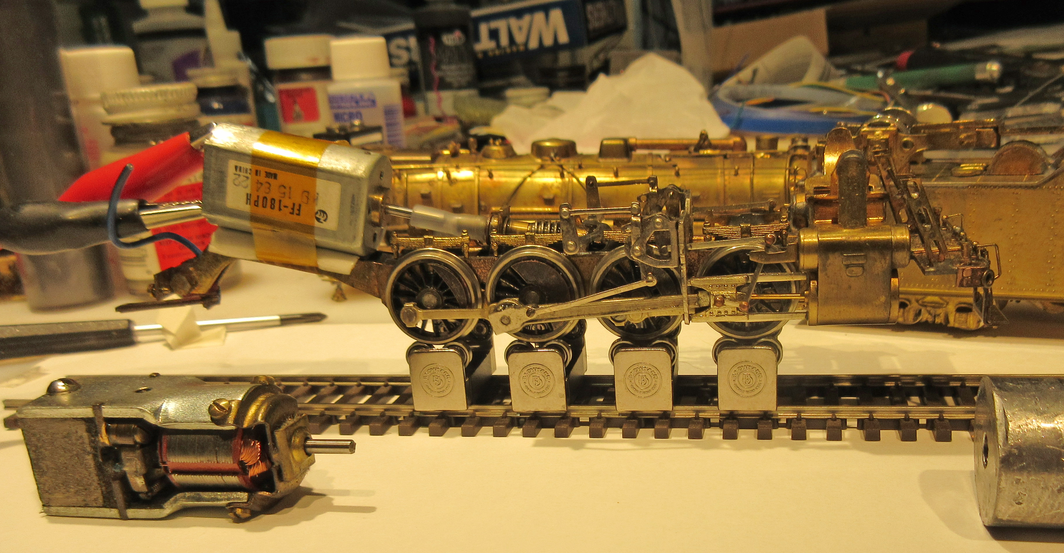
Yes, I believe it would. You really don’t have to get too fancy with mounting, in my opinion. You can see mine is stuck to the frame with a inch or so of double stick foam tape and a few wraps of strong Kapton tape.
The foam and tape also isolate the motor from the frame so less vibration and noise are transmitted. All the can motors I’ve encountered so far have isolated brushes, although that isn’t a real problem for open motors in most cases either.
Some guys will use silicone RTV. A metal bracket would be ideal, of course, but I don’t see the need as long as a good clean surface is prepared.
Go back to my first reply and click on the link for the summary of improving brass steam. There are some good pointers there. MR has had a few articles over the years, some dealing with DCC conversions, too.
With the motor removed, check for slop in the gear box, too. Sometimes too much lateral movement in the worm can be taken up with thrust washers. Clean the grease out and freshen it up, too.
UPDATE: I have decided to go ahead and replace the motor. I think I’ll wait and see how the gearbox runs before I try replacing it. Thanks everyone for your help.
Most replacement motors have two leads, so you will need to run a wire from the locomotive frame to one of them. Replacement motors generally do not “ground” through the motor frame.
.
If the locomotive runs in the wrong direction, just swap the wires.