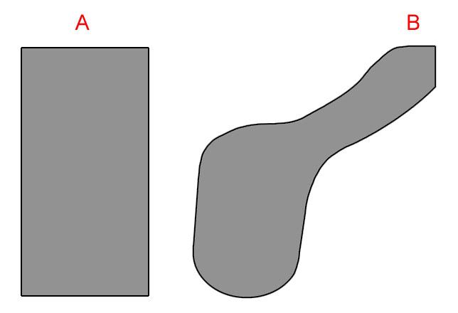
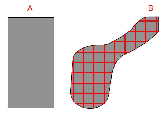
Although the table top is curved in illustration B, the grids are still squares and parts of the table top will overhang in places. In other words, draw a grid pattern over the top of illustration B. The grid doesn’t have to be squares or all the same size. They can be rectangles and/or triangles where needed. As long as you are using 3/4 inch plywood don’t worry about a little overhang. To attach a fascia, attach 2"X2" mounting blocks on the overhang where you need to fasten the fascia.
“L” girders system will work too, using less wood.
Just hold your horses until after you read the book.
That one is simple. One rectangle for the lobe, one for the upper leg and a triangle to connect the two following the method well explained in the above post. If you had to it, would be possible to have a curved end section using a bendable material such as bender board or masonite with radial supports on 12 inch centers from the rectangular section. I would also support it with a diagonal brace up from a cross brace near the bottom of the two legs supporting the rectangular section. Inner curves can be done the same way at a right angle corner.
EL, if you cut out every line except the ones outermost, you nearly have it right. Too many sticks as you have it depicted. Also, did you understand Big Rusty? Three (3) bench modules only, a large one under the bottom blob, with bracing, a triangular one coming off its top right, and then another smaller rectangular one going off at 45 deg to the upper right under the smaller arm/blob. In each case, they should not protrude from beneath the surface that you show in gray. Each would be a couple of inches or more smaller than the layout surface.
You’re getting there electrolove. If you are using sheets of 3/4" plywood and it covers the whole top, you won’t need a lot of grids. You might run into a situation where you want to install an under the table switch machine but a part of a grid is in the way.
More like this.
That’s grid type benchwork. If you were using another kind of sub-road bed like spline or cookie cutter, then you would add crossmembers where you need to support the sub-roadbed with a riser.
Can you dig it daddy-o?
However, if you are talking about making a FLAT 3/4" plywood table, I would not recommend grid benchwork. A flat piece of 3/4" plywood only needs bracing. That is where L-Girder construction is better sutied.
Think of two tables (divided at green line) made out of 3/4" Birch plywood (nice wood for spiking rail, no hard spots), 1"X6" or 1"x 8" Douglas Fir or oak girders (blue lines) and well braced 2"X2" Douglas Fir or oak legs*(dark blue dots). The attachment points for the fascia (brown dots) are usually a 2" cube of pine wood screwed to the plywood. The two tables would be bolted together through two pieces of 2"X2" hardwood lumber that has been machined square on at least two perpendicular sides each.
*If you want quick portable tables (assuming you can fit them through the door) you can use Foldable Metal Table Legs instead of wood.
Using the bottom diagram, you can make an open top layout with free-flowing edges by putting cross-members on top of and at right angles to the L-girders (or at right angles to the L-girders near “B”, and then keep the cross-members on the lower set of L-girders parallel to the upper ones. Trim the ends to give you the curves you want, then attach a Masonite fascia. You can use cookie-cutter, spline, or sheets of plywood for the roadbed, although the first two choices would allow better use of the benchwork for scenery below the roadbed.
I would run the L-girders from the narrow section all the way into the lower lobe, then add another L-girder in the bottom of the blob. The middle girder could be cut short in the blob.
(Sorry, this is all getting away from grid benchwork, but it’s not suitable for all situations.)
I’ll be the heretic and say I still think L-girder is a big old waste of wood. They key to good benchwork is that it is stable and doesn’t wobble. It’s NOT critical that everything measure to the tenth (that’s 1 ten thousandth of an inch for those not familiar with machining). Perfectly square? Not required. Close is nice, if only for a neater job, but we want a sturdy frame, not a piece of fine furniture (unless you are building a layout in the living room or something). Heck, I built what I have now exclusively with a hand saw, the only power tool was my cordless drill I used to drill pilot holes and drive screws. The only thing a power saw would have done is let me get it done in 1 day instead of 2.
Sorry Randy, I don’t get what you mean. Are you saying less wood is used in girder construction? Or are you saying L-girder is not stable?
We’re talking about a flat table. All that is needed is a way to attach the legs securely. There are stable layouts constructed on hollow wooden doors that only require sturdy legs.
Amen brother, I understand that and I agree 100%. Gussets and bracing of the legs are important. Both L-girder and grid construction depend on the ridgity of the legs and their attachment.
In the L-girder example I give above, the girders are just there to keep the plywood top from saging and flexing. How much can a 3/4" sheet of plywood flex anyway? Where ridgity is really needed is in the legs. I like hardwood or dense woods for legs because of the weight, splitting resistance and it holds screws tight. The attachment of the legs to the table top is the most important. .
The steel folding legs are stable when attached solidly and can support up to 800 pounds.
Like I’ve said in another thread, we’re not shooting train layouts to Mars.
But I think you misunderstood what I mean by machining Randy. I meant squared up with a planer or table saw. Something that only cost a buck or two at the lumber yard if you don’t have wood working tools. I’m not suggesting to anybody to chuck-up a piece of wood in a vertical mill.
In my example above, two tables are joined together. Would you agree that they need to be aligned well enough not to cause track mis-alignment? Either vertically or
Just to get everone back on track I show you this picture:
I’m talking about a construction method similar to this. As I mention earlier I will probably learn how to do it when I get the book I ordered. But feel free to help me before I get the book.
Ok, thanks for clearing that up electrolove. Open grid. No solid top.
No. I thought you were talking about cutting a sheet of plywood to cover the grid, thereby making it a table.
Using the grid example you posted, lay your track plan over the grid, you can figure out where the sub-roadbed needs support and where the risers need to be attached to the grid. You can change the size of the grids to work with your track plan. It will start to look something like the grid example I posted. Therefore you design your grids to fit the track plan.
Take a look at Sievers Benchwork. The grids are adjustable, so you can move an attachment point where you need it for the riser.
Risers are used in both grid and L-girder construction methods. They can be used in the cookie cutter method too. The risers only support the sub-roadbed.
L-girder is construction is different in a way. Kind of like a free form grid. It lends more versatility in the design of the whole layout than a grid. You’re not limited to a square or a bottom. It’s easier to add or move supports if you have to change things around to mount a switch machine under the sub-roadbed. And doesn’t limit the depth of the scenery (can support floor to ceiling scenery). However, because it is so versatile, it can get complicated depending on the track plan and scenery design.
That’s why grid is easier to understand. It has its limits.
What kind of sub roadbed do you plan to use and how wide would it be?
When answering Electro’s posts, you guys have to remeber that this layout will be built in a structure just a little larger than Madison Square Garden. Those grid layouts will work for normal layouts, but the layout he drew may well be indicating four foot by four foot (or more likely, meter by meter)grid sections, at which point the simpler designs no longer apply.
Coupla things, EL:
Don’t be too quick to dismiss plywood decking. I went whole hog with open benchwork everywhere, and then found that I could have easily used a flat deck for 90 percent of the layout, everywhere that proposed terrain lies at track level and above, using open benchwork only where terrain will lie below track level. This would have saved me half the cost and two thirds of the effort necessary to finish benchwork and move on. This may not apply to you, but then again, it may.
If you’re building as big as I think you are, might I suggest limiting yourself to no more than two benchwork module designs? One meter square (or if plywood and building foam are installed in 4 foot increments where you live, then 4’ by 4’) modules, and a similar module cut in half , then rotated as needed, will take you anywhere you need to go.
If you want the fascia and deck to curve, build the full and half to fit inside the intended layout design, and you can make the curves from 1x4 and luan and just screw them onto the edge of the closest full or half modules.
To see how many modules you need, draw your layout on graph paper or superimpose a 4 foot by four foot grid on a digital plan view, and you will then have every square module easily countable, every half module covered. and all the curved floaters pinned down by three corners and at least two of the sides.
Drawing in hand, I’d label the grids left to right and top to bottom, and label each module similarly, and then you’ll always have a reference for disassembly, not to mention phase considerations, like purchasi
When answering Electro’s posts, you guys have to remeber that this layout will be built in a structure just a little larger than Madison Square Garden. Those grid layouts will work for normal layouts, but the layout he drew may well be indicating four foot by four foot (or more likely, meter by meter)grid sections, at which point the simpler designs no longer apply.
Coupla things, EL:
Don’t be too quick to dismiss plywood decking. I went whole hog with open benchwork everywhere, and then found that I could have easily used a flat deck for 90 percent of the layout, everywhere that proposed terrain lies at track level and above, using open benchwork only where terrain will lie below track level. This would have saved me half the cost and two thirds of the effort necessary to finish benchwork and move on. This may not apply to you, but then again, it may.
If you’re building as big as I think you are, might I suggest limiting yourself to no more than two benchwork module designs? One meter square (or if plywood and building foam are installed in 4 foot increments where you live, then 4’ by 4’) modules, and a similar module cut in half , then rotated as needed, will take you anywhere you need to go.
If you want the fascia and deck to curve, build the full and half to fit inside the intended layout design, and you can make the curves from 1x4 and luan and just screw them onto the edge of the closest full or half modules.
To see how many modules you need, draw your layout on graph paper or superimpose a 4 foot by four foot grid on a digital plan view, and you will then have every square module easily countable, every half module covered. and all the curved floaters pinned down by three corners and at least two of the sides.
Drawing in hand, I’d label the grids left to right and top to bottom, and label each module similarly, and then you’ll always have a reference fo
Yep, I was confused [%-)].
MY first impression of the layout was a 4’X8’ sheet affair. Plus we (electrolove and I) were out of sync. Apparently we were writing at the same time. By the time I posted my message, electrolove already had posted new info. But I get it now. We are talking about a one big PIKE*
No loss though. It gave me an idea for a portable layout.
*a railroad term, not the fish.
Well, you couldn’t have picked a better and well known example. It’s certainly is bigger than a four foot by eight foot sheet of plywood.
The first time I became aware of spline roadbed was Howard Zane’s Piermot Division of the WM. He used a variant of spline sub-roadbed called spline & spacer. Pine cubes are used between the splines. Mr.Zane said he got 72 splines out of one 1"X8"X12 foot pine board. I want to try this and the Rick Rideout method.
The problem I saw though, was with Zane’s construction tip of using a hot glue gun to speed assembly. I wouldn’t trust hot glue to hold well during hot weather and over time. I’ve read some negitive feedback about using hot glue for spline assembly by others here in the Forums. One reply was about a club layout and a section had to be rebuilt after a few years.
Normally you use wood glue and clamp the splines as you go. You can only proceed as fast as the glue sets or with as many clamps you have. It can be a slow process.
I wonder if anyone has tried a brad nail gun to hold the splines? Probably would end up running into a nail where you need a hole for a switch machine. [censored]
It is also important to remember that Electro doesn’t live in North America.This means that he may not have access to all of the different construction materials we have here. I’m sure he can get the basics, but products like foam are almost out of the question. While basic plywood has to be available, items like Luan may not be, or they could have different names.
I suspect that Sweden has pretty good domestic lumber resources, but some items have to be imported, thus raising their cost. What may seem cheap and common to us could be a budget buster for Electro.
As for the grid, there is no need to make little squares. The point is to support the track, not necessarily be pretty. A 2’ x 8’ (or similar convenient metric dimension) with cross pieces every 16" should do the job. Additional structural members running parallel to the track are just wasted, because no risers will be attached to them.
The idea of having a simple basic module like a 2’ x 8’ is a good idea. something like that will fill the bulk of his needs. Of course there will have to be some embelishment and customization done to a number of these standard modules, but that’s no big deal really. Upper deck construction, and keeping it all fairly light weight is going to have to be considered as well.