This thread continues to fascinate me, and it has forced me to rethink my own existing layout design. Yesterday, I re-read my Kalmbach book on Freight Yards (Sperandeo) as well as the various likns that Paul provided in his earlier posts.
Despite the contentiousness of portions of this thread, many good points have been raised on layout design. I come away from this discussion with three principal conclusions.
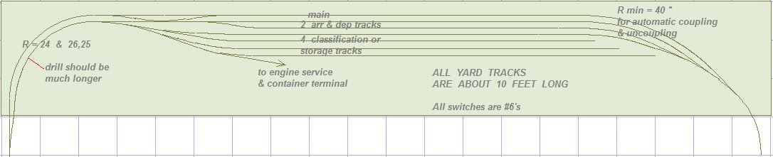
First, a yard should have a drill track, or switching lead, that is longer than the longest train so as not to block the main line track with an incoming or outgoing train.
Second, one or more arrival-departure tracks should branch off the end of the drill track and should be longer than the longest train so as not to block the drill track while classifying cars.
Third, a drill track should have an escape track, a crossover, to access the main line track when the arrival-departure track is filled, blocking access to the main line track.
One element of yard design that continues to perplex me is the order of the drill track and the arrival-departure track. In the layout design that Paul proposed fro BDP’s yard, it is the drill track (switching lead) that diverges off the main line and leads into the arrival-departure track. However, it seems to me that the usual order is the arrival-departure track first, followed by the switching lead track. That is the method shown in the Kalmbach book and Paul’s link to the Ten Commandments of Model Railroad Yard Design in the final diagram. That makes sense because the arrival-departure track is the track where a train can be received into the yard for classification and the track where a train can be made up prior to departure for other destinations.
On my own layout, a double mainline with crossover access from both the left and right to a double end yard, the crossovers lead onto the arrival-departure track just like in the final diagram in the Ten Comman
If you look closely at the crossovers at the upper left hand corner, you will see that an inbound train coming from the left will bypass the switching lead on the main, and then go into the A/D track.
While a train is arriving or departing, the four lowermost yard track can be switched from the switching lead. From the switching lead, you can also access the A/D track.
But the lowermost of the three double ended tracks cannot be used as an A/D track from/towards the left without going through the switching lead. In a pinch, it can be used as an A/D track from/towards the right, though.
Good read and very well thought out. Had to read it a couple of times and actually put myself on a train to simply figure out what you were saying. All is good.
I think you can really put a lot of thought into a yard and when you finally get the one you want, something else pops up. Is there a perfect yard out there? I dont know. Do I want it? Yes if applicable.
After my sons helped me with a little bit of bench work last night and after they went to bed, I did layout my track to the design Paul had posted and I modeled and it will work. I have 24* coming into the “pinwheel” (if that is what it is called) so my 6 axle engines will be ok. My only problem I have is that I was going to use all manual Caboose Ind throws (for more of a hands on layout) and the turnouts are so tight that I wont be able to use them. For those 3 turnouts I can use under table switch machines. It works out the my 16" center boards will not interfere with them, which is a miracle.
The rest of the design of the layout is coming along nicely. I am at a stand still right now because I have been busy but I need to decide what else I am going to on the layout that the trains would need to service.
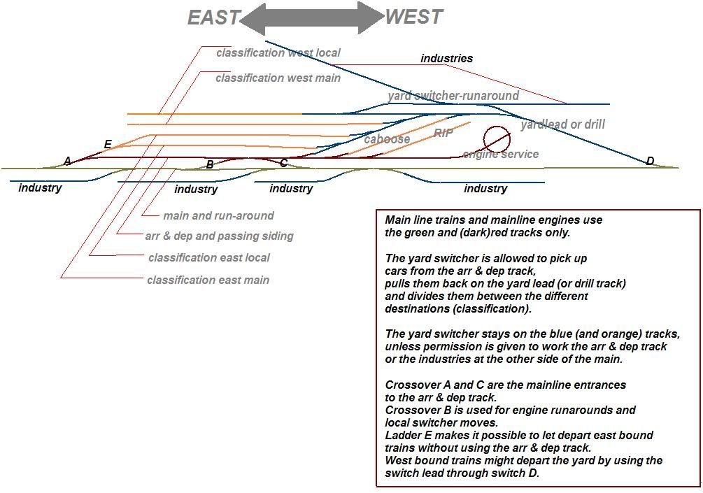
you are a full100 % right; but if you read more about yard-design (eg freight yard-design by Andy Sperandeo) you could see extra connections were often made. So freight trains could also leave or enter the enter the yard by the switch-lead. Of course the dispatcher or tower-man had to take these decisions. Direct access to the main (to the east) from some of the classification tracks have the same function; flexibility designed in.
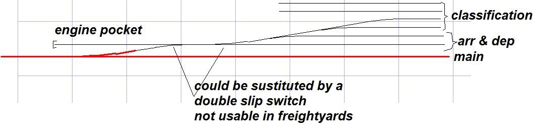
You could omit switch D, leaving the yard-lead as a stub-track. Or connect it with the main by a cross-over, creating an extra switcher pocket. The yard goat could wait here till a freight heading for the main has passed. The same applies for the ladder E. Stein suggested to add a switcher pocket there as well.
BTW all these tricks are only needed if it is dictated by the amount of traffic. On a just a few-trains-a-day branch the main would be used as a drill-track as well. If the OP wants to run just one train at a time these designs are not appropriate. When more then one train is running at the same time, it might be wise to think about the consequences, not only in the yard but also for the remainder of his layout.
Tony Koester found out, while researching his NKP, switchers worked with half trains for safety reasons. The engineer could not see well the switch men on the ground at the other end of the train. Lance Mindheim’s saying, the more you know about real railroads, the less track you need for realistic operation applies here too.
If you wind up using under table switch machines, I encourage you to consider Tortoises. If you buy a number of them at once, the expense will be considerably reduced, and the resulting operation is so much better than with some of the other under table switch machines like the Atlas machine.
Before giving up on Caboose Industries manual ground throws, however, have you considered rearranging the throwbars from left to right, or right to left, as the case may be. Using Paul’s diagram, the turnouts should not be so tight as to eliminate manual ground throws from consideration.
I did look at trying to reverse the throw but I dont think I can without doing much harm to the turnout. If someone has done this I would be open to suggestions on how to. How I have it in my blueprints is that the turnout is connected right to the diverging route. Is this correct or do I need to add a small piece of curved or straight track in between my turnouts? If you think there should be room then I need to go back to the drawing board. I would rather use some sort of manual throw instead of electrical throws to run those.
Sorry - Rich is right. I must somehow have dropped a “yard” there - I meant the “third double ended yard track” (i.e. not counting the main). Track no 4 from the top of the drawing.
Well here is the vast majority of my layout. I am still contemplating putting in a spur or 2 on the bottom leading to some industry but what that is I am not for sure yet. I dont want to put the Inter Model yard there because I am planning a small town and maybe some farm houses.
In this Layout I did what Paul had posted out of the magazine. Like I said in my earlier post, I dont think my Caboose ground throws will work with this unless I need to add a short piece of track in between the diverging route and main line connections on the turnouts. I did move the turnout on the left down more to allow more room in and out of the yard.
In this one I went ahead and added a Shinohara curved turnout to connect to one of the sidings just to add another run around if needed.
not bad at all, i would make the yard lead way longer, so the tracks at the left could be used as a double track main; all the way down to the second station.
Beside some esthetic comments you could add a real staging yard. It has not to be build yet, thinking ahead where you could place it is what i have in mind. As I understood you have access all around the layout as well, so it would be easy to find a place for it.
IMAO the tracks are to close to the edge, except at the bottom.
On the left side and bottom of the layout, it is right against the wall. Only accessible from the front. The top and right are accessible from both sides but I plan on putting up a scenic background on the right to hide my work bench.
I re-did this and moved the turnout on the left down more. Is this where you were talking about moving it? Or move it on around the corner.
As far as a staging yard I could look at adding something later on to where the yard is now or maybe even behind my scenic background on the right. But I can do something later with that if need be. As far as the track being close to the edge, I think you are correct, I will move them in.
Here is what I did. Let me know if this is what you meant.
I’m betting that Paul wants that switching lead to come all the way down to the bottom left corner even if that requires a right hand curved turnout to make the connection to the main line. Then the tracks to the ethanol plant could diverge right after the turnout from the main line that would form the switching lead. That would make sense in order to make your switching lead longer than your longest train so as not to block the main line.