If you take a close look at the throwbar portion between the two rails, there are two plastic tabs holding down the metal points. Those plastic tabs can be carefully and gently lifted out of position with a small screwdriver or the dull side of an Exacto knife blade. Once lifted out of position, free of the metal points, the plastic throwbar can be reversed so that you have room to install a manual ground throw. I never met a throwbar that could not be reversed, so consider giving it a try. Once the throwbar is reversed, simply press the plastic tabs down on the metal points once again.
I did look at trying to reverse the throw but I dont think I can without doing much harm to the turnout. If someone has done this I would be open to suggestions on how to. How I have it in my blueprints is that the turnout is connected right to the diverging route. Is this correct or do I need to add a small piece of curved or straight track in between my turnouts? If you think there should be room then I need to go back to the drawing board. I would rather use some sort of manual throw instead of electrical throws to run those.
Brad,
What brand of turnouts are you using?
Rich
Most of my turnouts are Atlas #6’s with a few #4’s.
Brad
Brad,
If you take a close look at the throwbar portion between the two rails, there are two plastic tabs holding down the metal points. Those plastic tabs can be carefully and gently lifted out of position with a small screwdriver or the dull side of an Exacto knife blade. Once lifted out of position, free of the metal points, the plastic throwbar can be reversed so that you have room to install a manual ground throw. I never met a throwbar that could not be reversed, so consider giving it a try. Once the throwbar is reversed, simply press the plastic tabs down on the metal points once again.
Just take your time and use a tiny screwdriver or the dull side of the blade on an Exacto knife. Lift up the plastic tab and move the metal point away. Then, lift up the other plastic tab and move thst metal point away. Then, remove the throwbar and replace it in the opposite direction and reapply the tabs. A guy at the LHS showed me that some years ago, and I have always been grateful for the tip.
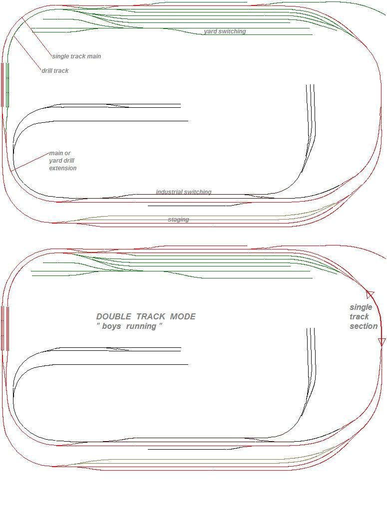
On your other point, it you can pull it off, by all means set up the layout as a double mainline. Each one of your sons can have his own track, and you can work the yard. My entire layout is a double mainline, and it is a blast to operate. Maybe your wife can be the yard master. [swg]
I will be operating the layout in DCC. I have a Digitrax Super Empire Builder Extra on order and just waiting for it to come in. It has a 5 amp power supply. I did have the MRC Prodigy Advanced 2 squared but it was only 3 amps. Plus a couple of guys I know have Digitrax, so that way if I have questions I can give them a shout.
I plan on breaking it down into 2 divisions right now but possibly a 3rd, havent decided yet…
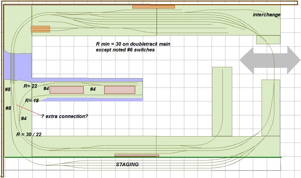
just a vision, two trains can do lap running at the same time, a pretty short single track section over the lift-out remains. Loads of switching possibilities; switching the dock can be done completely independent from main line running.
BTW the second main is in reality the yard lead, used differently if needed.
The radius of the main is 30", IMAO a better choice for modern equipment.
I really like the lift out. To me, that makes more sense than the duckunder. Only a single track to deal with thanks to the creation of the peninsula. Nice.
I also like the addition of the staging area - - too much space wasted at the bottom in the original plan.
The longer switcher lead track solves the blocking problem though I question whether #8 turnouts are really needed.
The river and the interchange are interesting additions - - added visual interest. We will see if BDP likes either of those ideas.
This proposed layout plan will be a challenge for BDP’s two sons. They may be too young to be able to cope with some of the nuances, but they can always grow into it. If it were my layout, I would stick with the concept of a true double mainline. That will permit the kids to each operate their own train on their own track without adult intervention.
But, hey, who asked me? It will be interesting to get Brad’s response.
I really like that layout. It seems to flow nicely together. I like the lift out option you have put in. In your diagram would the staging be hidden or would it be open. I guess what I mean about that is would there be a back drop between the staging yard and the rest of the layout. If there is then it would be a problem for me to possibly access this because I would put that part of the layout against the wall. If there is not then it would be ok.
I dont mind ducking under mine right now because I am on 5’8" tall so it isnt much for me to duck under. Plus I duck under things all the time at work so I am kinda used to it.
As I was working on getting a double mainline implemented I came to the problem on the upper right of my layout and trying to tie in the second mainline into the pinwheel on the right side of the yard. I thought well I have to put in a switch right before the yard and at that short point there is only going to be 1 mainline run. Then I see you have the single main for the lift out and that it is ok to have a short run of a single main as long as it is signaled right for the trains.
I will finish up my layout and see what you guys think.
Well I think this is pretty much all I am planning to do now. I am going to go through the Walters book and see if there is anything that I want that is in the book that I need rail service to. It is about 300’ of track (have to get a few more pieces) and 31 turnouts. Let me know what you guys think.
I am using DCC so I dont think that there are any reverse loops anywhere. Was trying to stay away from that. LOL
That is ok. I made my yard bench work 36" because I knew I could access it from both sides. All other sides are 30" because with my bench work height that is about the max for me reaching over the layout only being 5’8" tall. I appreciate the work that you did and the results in the short amount of time you did it.
No, there are no reverse loops. Would you like us to create one? LOL.
By now, you are probably tired of suggestions, but that never stopped me. If you truly want a double mainline, you need to rethink part of your latest track plan. That now infamous switching lead, the inner track running up the left side, is really not a mainline track. So, those two crossovers at the top of the track plan are connecting the switching lead track to the main line, a single track. That’s why you are having trouble on the upper right, coming around that pinwheel. And the continuation of that inner track coming up from the bottom right is unnecessary, shoulda left it like it was before.
What you need to do to create a continuous double mainline is to add an outermost track all around the layout with crossovers at appropriate spots (1) to get from the outer mainline track to the inner mainline track to reach the switching lead track on the left side and (2) to get from the inner mainline track to the outer mainline track from the switching lead track on the right side.
Well I think this is pretty much all I am planning to do now. I am going to go through the Walters book and see if there is anything that I want that is in the book that I need rail service to. It is about 300’ of track (have to get a few more pieces) and 31 turnouts. Let me know what you guys think.
I am using DCC so I dont think that there are any reverse loops anywhere. Was trying to stay away from that. LOL
No, there are no reverse loops. Would you like us to create one? LOL.
By now, you are probably tired of suggestions, but that never stopped me. If you truly want a double mainline, you need to rethink part of your latest track plan. That now infamous switching lead, the inner track running up the left side, is really not a mainline track. So, those two crossovers at the top of the track plan are connecting the switching lead track to the main line, a single track. That’s why you are having trouble on the upper right, coming around that pinwheel. And the continuation of that inner track coming up from the bottom right is unnecessary, shoulda left it like it was before.
What you need to do to create a continuous double mainline is to add an outermost track all around the layout with crossovers at appropriate spots (1) to get from the outer mainline track to the inner mainline track to reach the switching lead track on the left side and (2) to get from the inner mainline track to the outer mainline track from the switching lead track on the right side.
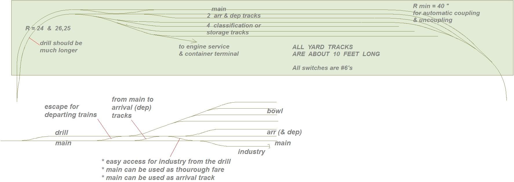
It is interesting to note that John Armstrong makes no mention of an arrival/departure track in his book. He does mention “receiving” tracks and yards and “departure” tracks and yards. He more or less relies on the longest classification track to serve in that capacity.
He places a lot of stress on the switching lead track. As he notes, “The key item for efficient operation is the switching lead clear of the main track”.
In addition to the switch lead track, Armstrong also stresses the use of a thoroughfare track and a separate caboose track as vital to the efficient operation of the yard.
While Andy Sperandeo, in his more recent book, also stresses the importance of the switching lead track, the thoroughfare track and the separate caboose track, he continually stresses the need for a separate arrival/departure track for efficient yard operation.
sufficient arrival-tracks are giving the dispatcher an easy life; his road is not blocked by waiting trains. At the very same time it would be great for the switch-master to have tracks where cars can wait till departure time, without fouling classification. Extra bowl tracks or a sufficient number of departure tracks are often needed to keep yard operation flu-ed.
Real yards are gigantic; what to model? Using classification tracks as departure tracks is one trick. Spares the yard goat some extra moves too. David Barrow always adds an extra cross over between the main and switch lead to let escape departing trains directly from the classification tracks.
As I mentioned previously, this thread has really caused me to look deeper into the whole subject of prototypical freight yard operation.
In addition to the great links already provided on this thread to some excellent reference material, I came across a digital download from Kalmbach Publications for $5.95 that provides a compilation of 16 prior articles from Trains Magazine about freight yards. Here is the link:
This digital download, in the form of a PDF document, includes a host of wonderful photos and diagrams of freight yards over the past 75 years. Of particular interest to me in this digital download is a 2-part series from the June and July 2002 editions of Trains Magazine that covers the design of a prototypical freight yard.
I highly recommend this digital download to all who are interested in designing a prototypical freight yard.
Sorry for the delay in responding, but been extremely busy with other things than the layout.
I think I have finalized my layout and I feel happy about it. Going to serve my needs for now. I maybe in over my head with the size of it but I wanted to go all out. My regret it but hope not. I have to finish my bench work which is almost done, just need to secure the top plywood pieces.
Here is what I have for a finished product. I had to make a few minor changes because I went with 32" radius on the outer main line and then 30" radius on the inner main line. I did this to accommodate 89’ auto racks and box cars. Didnt want it looking to funny going around curves on my 24* and 22* curves. All of my curves are no less than 22* which I am happy with.
Thanks for all the help and even though touchy at times I appreciate the advice.