I tested the transformer and noted three interesting things:
(1) The reverse switch does not interrupt the current as much as it cuts the current in half. So, it does not get near zero when the throttle is set at higher speeds. Is this the correct function?
(2) Both variable post pairs (both A&B) “leak” current when the throttle is set to “stop.” They leak about 0.5 volts even when the transformer is turned off (but plugged in), and they leak 1.0 volts when the power is on but the throttle is set to stop.
(3) There is not much smooth voltage increase with the throttle increase: it jumps from about 2 volts to 7 volts, and then smooths out as it increases the rest of the way to its maximum (which is 17 volts as opposed to 15).
I have tested the unit for continuity problems in terms of current leakage where it shouldn’t be present and all seems sound that way (besides the .5 volts leaking to the variable posts when the transormer is turned off…
There doesn’t seem to be a “reverse” switch on the 12B. What are you pressing? If it’s the reset button for the circuit breaker, that might open the breaker; but it would leave the lamp in series with the transformer. That might explain what you are seeing.
You talk about leaking current, but then give voltage numbers. What are you measuring and how are you measuring it? What kind of meter, connected how, and with what else connected to the transformer?
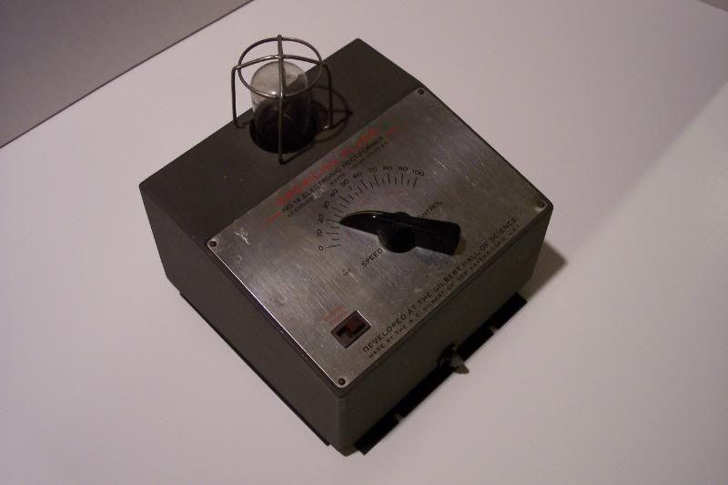
Regarding the transformer: short of posting a photo, you will have to take my word that the transformer is an AF model #12B (it says so on the face plate) and has both a “reverse” switch and a “reset” button, along with an on-off switch, two lamps, and two power levers.
Regarding “current”: Oopsie, I was misusing that term. In all cases, I was referring to volt testing (not amps) using a basic multimeter set to AC voltage. The operating output was tested (and “leaking” discovered) by plugging the transformer in and attaching the meter leads to the appropriate posts with nothing else attached. The “leaking” refers to voltage readings that came from the variable posts when the transformer was either plugged in but turned off, or turned on but with the throttle set to stop. I would expect a reading of zero when the throttle was turned to stop, particularly when the transformer itself was turned off. But maybe the presence of .5 or 1.0 volts at the posts is not unusual even when turned off.
Hi, sorry about the bad information I gave you regarding the 12B, my books only showed the one without he reverse switch. But many of us have learned that there is a 12B made with a reverse switch.
Considering all of my recent difficulties with the reversing unit on both my steam engine and my diesel, I have to say that the reversing unit is the Achilles Heel of the American Flyer electrical system.
The problems described by the author of this thread are remarkably similar to the problems I faced with the reversing units on my two engines.
Knowing nothing more about his 12B transformer than what is being reported here, i would conclude that there is nothing wrong with the transformer but, rather, something is wrong with the reversing unit.
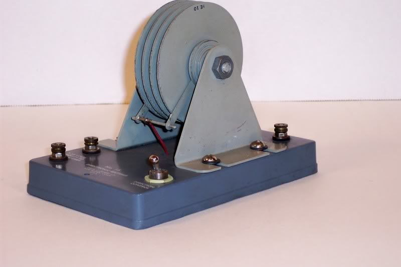
The first thing I had to do was lubricate and clean the pawl, then replace the upper and lower finger boards, then tighten the metal tabs that hold then finger boards in place.
I am still experiencing intermittent failures of the reversing unit to cycle properly into the forward position. Close inspection of the reversing unit leads me to believe that the pawl still sticks on occasion or at least fails to engage the “clutch” (or gear) and turn the drum.
If I could start over, I would have replaced the reversing unit altogether or maybe purchase a Dallee Electronic E-Unit" (sorry Timboy, you asked us to cease and desist with that term, but that is what Dallee calls it).
As I say, I consider the reversing unit as the Achilles Heel of American Flyer.
If it is similar to the E relays on Lionel engines, you can usually free it up with a shot of WD-40. Wipe off any excess before you apply power. Bruce Baker
I agree that a lubricant like WD-40 or something similar will free up the pawl. But, sometimes, with age, the entire linkage mechanism that controls the pawl seems to lose its firmness, or so it seems. In my case, while the pawl and its linkage seems to move freely, the pawl does seem to engage the gear firmly every time in order to rotate the drum.
Ok, my tester is a $20 radio shack #22-810. The more I use it here the less I trust it for this task.
I tried testing two ways: touching the probes to various places on the posts, and securing wires to the posts that are connected to alligator clips and attaching the clips to the tips of the probes.
Why test two ways? Because using the probe approach, I got different readings in different places on the post. And sometimes the reading would change around while I held the probes perfectly still. Sometimes it would start iwth a reading of 2.0 v or so, then jump around a bit while heading down to zero. The strongest readings I got was on the end of the post screw cap. Actually unscrewing the cap a bit and touching the threads led to lower or zero readings. I got readings at times and places of 0 or 1.5 or 2.0 that stayed steady, and also lots of readings in between as it jumped around.
Wheee!
So I tried the bare wire on the post to alligator clip approach. There I got consistent readings of 1.5 at stop and 0 at half way. Except I noticed that it still read around 1.0 to 2.0 v when I had disconnected the red lead, and only the black lead was still attached. I waved the red lead around, stuck into in my pocket, hid it under the table: still reading 1.0 or so AC volts with only one lead connected to the transformer.
Double whee!
Ok. So should I buck up and get a better meter? I can’t drop $400 on one. So what’s the minimum price level and best maker to buy in a lower price range? (I ask this knowing it might launch a forum debate about the best meter, but hey, I am not in a hurry).
Thanks. I am actually enjoying my muddle through here, I hope you are too.
Your problem seems to be your meter. Not that it’s too cheap, but that it’s too good. A more expensive one will probably have an even higher input impedance; but yours is already too high for what you’re trying to measure. For example, when you put the probes on the transformer output and turn the control all the way down, you are measuring the voltage on a wire that isn’t connected to anything inside the transformer. Because your meter isn’t putting any significant load on that wire, it is picking up whatever stray voltage is being capacitively coupled to the wire. When you turn the handle up half way, the transformer secondary connects that wire to the common through the much lower impedance of the secondary winding and suddenly you measure zero voltage.
The various voltages you are measuring as you wave the probes around are due to the same kind of effect. If you had a traditional passive analog meter, you wouldn’t be seeing that stuff. You can simulate that situation by connecting a resistor, perhaps 1000 ohms, between your probes while you take your measurements. You should get something much closer to what would make sense.