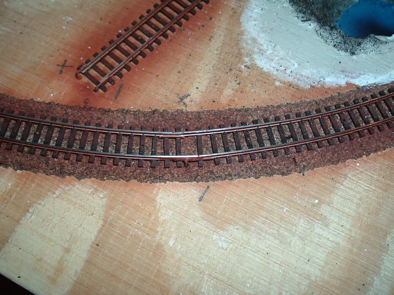
Before laying the main on my railroad I soldered 2 lengths of flex track together hopeing there would be no kink where the 2 lengths meet. However that is not the case. The track has a small kink there that derails some of my locomotive and derail my desire to do more work on the railroad. I am using Atlas code 100 flex track on an 11 inch radius curve if it makes a difference. Here is a picture of the kink causing the problem. Any and all help is welcome.
Even when you solder the joint, you want to do everything you can to keep the pressure off of it. Since it looks like you used track nails to hold it down, you might try adding one in the hole nearest the joint. But before you do that, you can try to get the kink out. I’m assuming that there is solder in the joiners under all of the rails. Get something to push on the joint, and a hot soldering iron. Warm up the joint, push the kink out, remove the heat, and wait a couple seconds before removing the pressure. Then do the other rail.
When you do the joints initiallt you need to make sure the solder has well and truly flowed into the joiner and around the rails. And you need everything to be as snug as possible. That’s a tight curve, so you’ll need to be gentle as you bend it, and give it as much support as possible.
I always lay my (Atlas N scale code 80) track first to make sure it lines up correctly. Then I do the soldering, and remove any exsess solder on the inside of of the joint then file it smooth.
The problem with that is if you solder off-layout you have to remove sooooo many of the ties.
This is because there are no ties there to hold either the gauge of the track or the track to the roadbed.
Try soldering in place so the track lays better and not so many ties are destroyed in the process.
Increase the offset of the joint on the two rails so one rail is solid while the other one joins and vice versa. To do this slide the rail from one section of track into the ties of the other.
It’s been a while since I laid the track on my N-scale layout, but here’s what I remember doing. Set up the flex-track so that the movable rail is on the inside of the curve. Try to avoid joining flex-track in the middle of a curve, but that’s not always possible. Establish your curve, and in those cases where the joints meet in the middle of a curve, let the flex-track go straight and then solder the joints. After the solder takes, it can be put back into place and secured.
Right, I forgot this point. Put in the curve, and remove the ties where the joint is when it is curved. That way you avoid the larger stretch of removed ties.
I had the same trouble a couple of years back. I think my issue was the same as yours, namely the 11 inch radius is too small for the flex track. At that radius, I always had a kink. I tried the same method but with a 22 inch radius, and it worked fine. Since then, any time I had a radius 12 inches or less, I used sectional track for the curve. Don’t know if this helps, but this has been my experience with this particular topic.
When joining two pieces of flex track, I prefer to trim the rail clamps from one tie at the end of the flex track section where the rail joiner will sit, rather than cutting the ties out, then joining and soldering. I find this helps maintain the gage and looks better (to me) than gluing the ties back in later.
As MAbruce mentioned above, the movable rail should be to the inside of the curve. I then place the track and for the curve, letting the movable rail extend at both ends. Once the curve is established, I trim the extended inner rail to meet the next section.
From looking at the picture you included with your post, it appears you removed the tie clamps from several ties. This may have caused your problem. It also appears that you might have placed the power lead after the track was pinned down. I prefer to place power leads away from the rail joiners to prevent reheating them and allowing the track to move as a result.
As I look at the picture, it seems that the track joint is closer to the outside of the roadbed, then flexes back towrds the inside of the road bed as if though iif the jointed section needs to be moved slighlty inward.
Joe Fugate has an EXCELLENT VIDEO about laying flex track, downloadable through MRR .
I HIGHLY RECOMMEND purcasing it, and downloading it. It’s about 5 or 6 dollars but worth it.
Next, what you want to do is to lay your TWO pieces of FLEX TRACK out straight, REMOVE about 2 TIES from the end of each one, then join your track so both rails are even, slide on your track joiners, THEN SOLDER them together, THEN lay your track on your curve, and carefully watching for kinks.
If you aleady have ONE PIECE of FLEXTRACK layed down in place with the radius curve alreay established, follow the above procedure as far as removing two ties at both ends where they will meet. THEN gently bend your track to the desired radius, and THEN marking your track as one rail will be able to slde(make sure it is on the iNSIDE of the radius curve), then cut your rails so they match up with both rails squared and even to each other, then slide on your joiners, and and use pins or tacks to hold your SECOND piece of rail in place, THEN SOLDER it.
I was able to improve the situation by desoldering the joint and pressing them straight with a flat blade screwdriver. Finally, I installed additional track spikes on the joints to help brace them straight. Thanks again to everyone who replied all of our advice was greaty appericated.