Most turnouts require something to hold the point rails in place, either a switch machine or some sort of manual control. The notable exception is Peco, which has a spring built into the turnout and holds quite well with no additional hardware.
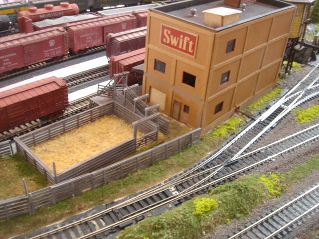
I’ve hidden a number of larger Atlas electric switch machines under scenery. The turnout in the foreground has a “scenic cover” and the one off to the right has an extended throwbar which reaches into the Swift plant where the machine is located.
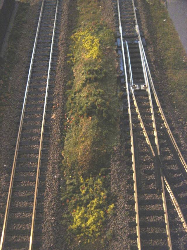
This is a close-up of one turnout cover. To make these, I put a couple of small pieces of foam scrap on the machine to create “dead space” and then cover that with clear plastic wrap (like Saran Wrap.) Then I make a cover with plaster cloth. After the plaster cloth sets, I remove the cover and discard the plastic wrap and foam scraps. The plaster cover now forms a shell that I can cover with scenic materials.
Please excuse my ignorance as I model in HO and don’t know much about N scale equipment. but in HO, manually thrown turnouts can be operated by a little bit more prototypically correct ground throws. What is done is to simply remove the manual switch mechanism that comes with the turnout, trim off the screw tabs (or scenically hide them), insert headblocks (extended ties for the ground throws to be mounted on) and follow the manufacturers’s instructions for mounting. Caboose Industries makes these groundthrows for HO but I don’t know if such a thing is made for N scale.
Caboose industries makes N Scale ground throws as well as HO scale throws. Whether you need a manual throw, however, depends on what brand of turnout you use. Atlas turnouts need something to hold the points if you remove the manual throw. They make an under-table version of their switch motors if you want to go that route. PECO turnouts have an embedded spring so the points will click and stay where you put them so you don’t need a separate manual throw. Lefty
My manually operated points are thrown by electrical switches (slide or toggle) mounted at the fascia line below sub-roadbed level, linked to the points by a simple mechanical linkage.
The points are driven by the upper arm of an Anderson link (a Z-shaped bent paperclip in a brass tube lined drilled hole) with the lower arm held in the ‘normal’ position by a suspended weight. Throwing the control switch pulls the Anderson link, raises the weight and moves the points to the ‘reverse’ position. (Normal - the preferred route; reverse - the alternate route. Terminology comes from manual interlocking practice.) The connector is a length of fishing line guided by screw-eyes from weight to Anderson link arm to control switch. The weight may be a fishing weight or something similar. The fishing line is always in tension - no trying to push a rope - and may be quite long.
Where the distance to the table edge is short, I sometimes mount the toggle or slide switch at table-top level and connect it to the throwbar with a bent paper clip - bend including a ‘wishbone’ to compensate for differences in the length of throw.
The switches are always DPDT - one set of contacts powers the hot frogs of the turnouts, the other is available for signals and panel indicators.
Chuck (Modeling Central Japan in September, 1964 - frugally)