Not necessarily. If he turns his drawing into a double mainline dogbone, he can exit the end loops onto the other mainline and then add a crossover from one mainline to the other mainline mid way between the ends of the layout and wire everything including the crossover in phase - - no reverse loops.
In fact, that is exactly what he should do to increase the capacity for running more than one train at a time. My layout is a double mainline with crossovers at various points to enter/exit yards and spurs and sidings. No reverse loops on my double mainline.
As for your automatic-switch question, spring switches could be an option. They’re not electrically operated, so that would save you some of the headache in wiring your layout.
Hmmm. I’m no expert but it seems me that this crossover configuration produces the need for a reversing section (in the blue circle)? Are you referring to a different crossover configuration?
That’s why I said not necessarily. It all depends upon the actual track configuration. In your drawing, you are correct, a reversing section would need to be installed to avoid dead shorts. However, if the double main line proceeds all around the layout, one mainline parallel to the other, then no reverse polarity would occur as a result of the crossover.
Your drawing is not actually a double main line, but rather a continuous single mainline running around the entire layout. A true double main line provides all kinds of options for maintaining and/or changing the direction of multiple trains.
I’m pretty sure OP Starman is planning to have two return loops connected by a “double track” mainline (aka DogBone). It’s a very popular configuration for good reason. I just wanted to point out that adding a crossover along the double track mainline introduces a reversing section (albeit with the addition of better operation potential).
Doug, I totally agree with you, and I wanted to be careful not to appear to be criticizing or challenging your statement or drawing which was accurate.
Let me get some Honey-Do things out of the way this morning and I will draw some diagrams of how a double mainline dogbone might be constructed and wired.
This track plan is intended for DC operation hence the Cab Selector.
If you decide to go with the crossover you will need an auto reverser and some form of switch control.
The switch controls can be automated; with detection circuits, it can be wired DCC; controlled through the DigiTrax controller, DC; with two remote switches, or can be manually thrown.
The manual throws would be the cheapest option but with little hands might not be the best option.
When I converted my pike from DC to DCC I kept the turnouts DC. I have a Wye in the center of my loop that requires the use of an AR unit.
This combination works well for me.
Again, thanks for the update and good luck with the project.
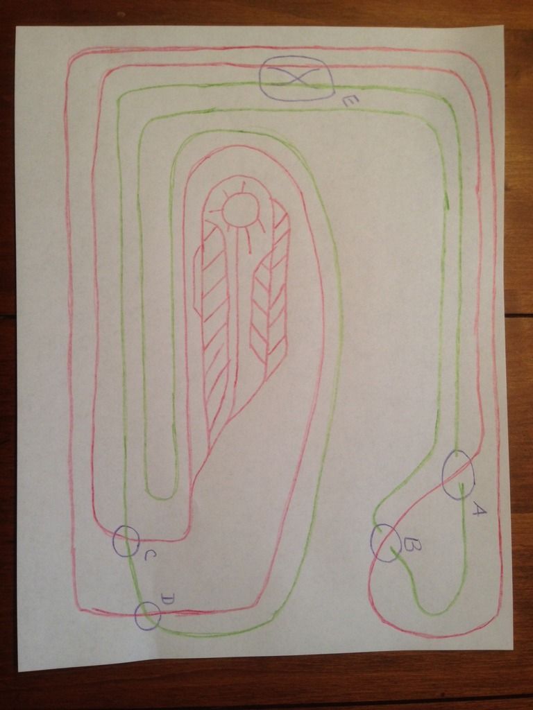
Here is a general view of the first phase of my track plan. The second phase will be the yard. I am still working on that design and that will be a topic for another day as to how to wire it.
Based on all I have heard, I have decided to run two double main lines. Main line RED and main line GREEN. Points A and B on my plan are not a problem as main line RED will be elevated and main line GREEN will run under RED. Then there are points C and D where I want main lines RED and GREEN to cross each other. There is no elevation change here. Point E is where I would like to be able to switch trains between the two main lines when I want. Would points C and D be a better place than point E for switching between main lines? Perhaps using turnouts, activated by switch motors (non-automated) would work?
I hope I have been clear, but please ask any questions you may have.
My questions is exactly what do I have and how to wire it. I know about bus lines and drops, but I am not sure where I will need a reversing loop or anything of the sort to make this track plan work. I would like to have this plan automated as much as possible so I can power up trains on main lines RED and GREEN, when the grandkids are over, and they can just watch the trains run. At other times, when my son and I am operating, I am willing to throw turnouts, etc. as needed to move the trains around.
from your photo library, click on the photo you want.
When it comes up on screen on the right side you’ll see a window that says codes. Click on the text box that says, “IMG”. It should auto copy to your clipboard.
I can’t mentally slap your track dimensions 13x19’ on this drawing. It’s entirely possible that most people can, I’m just talking about me personally. I realize it’s not to scale but the green hairpin turn at the start of the turntable yard doesn’t look doable in this perspective.
I hope this works. I have copied my post of earlier today so it is whith the picture.
Here is a general view of the first phase of my track plan. The second phase will be the yard. I am still working on that design and that will be a topic for another day as to how to wire it.
Based on all I have heard, I have decided to run two double main lines. Main line RED and main line GREEN. Points A and B on my plan are not a problem as main line RED will be elevated and main line GREEN will run under RED. Then there are points C and D where I want main lines RED and GREEN to cross each other. There is no elevation change here. Point E is where I would like to be able to switch trains between the two main lines when I want. Would points C and D be a better place than point E for switching between main lines? Perhaps using turnouts, activated by switch motors (non-automated) would work?
I hope I have been clear, but please ask any questions you may have.
My questions is exactly what do I have and how to wire it. I know about bus lines and drops, but I am not sure where I will need a reversing loop or anything of the sort to make this track plan work. I would like to have this plan auto
Henry - My drawing is not even close to scale. I just made a basic drawing for the purpose of talking about how to wire it. I have my bench work covered with white paper and the track drawn real close to where it will actually be. I believe it will work, or at lease I hope so. [:D] Starman