Hi Guys,
Since I have no original powerpack to power my trains (didn’t found an option worth paying a lot of $$ for) I’m wondering how the horn function is activated.
I know it has something to do with a DC signal, but how excactly does it work?
Also about the Bell function. I’m expecting a locomotive having Horn and Bell (electronics) so I would like to make some device to mimic the signals coming from an original transformer.
Thanks for helping in advance, it would be nice to use those features…[:D]
The whistle applies a positive DC offset to the AC track power, and the bell a negative DC offset. An amount of 3 volts to pickup and .75 volts to maintain is usually considered acceptable. The easiest way to get this is to first put a diode in series with the track, and then quickly add a low-value resistor parallel to it.
Daan, this topic was discussed at length back in March. Most of it had to do with trying to use dry cells to blow the whistle. The best approact appeared at the end:
"I use a different approach. Get 12 6 amp rectifier diodes,2 European style barrier strips,and 2 push button swiches all available at Radio Shack. Mount the diodes so you have an array 6 in each direction… Jump wires accross the array at both ends. Put this assembly in line between the hot wire and the track. Wire push buttons so each one jumps 5 of one side of the diode array. One button will acivate the bell and the other will activate the whistle. Since each diode drops the current about .6 volts,this hookup would alter a ZWs output from 6-20 volts to 3-17 volts AC allowing smother starts to modern engines. Activating the bell or whistle would give you about 1.5 extra volts to the track to compensate for sound activation. For Postwar tenders you can make the diode array longer giving more compensation so the train doesnt slow down when you activate the whistle. The diode array described is good for 120 watts to the track,very ample in most cases. If you need more capacity you can simply double the Diodes. Use 16 gauge wire or heavier. No soldering is required as the diodes mount easily in the strips.
"Dale Hz "
"Bridge rectifiers are a handy way to get the effect of two diodes in one package. Use the + terminal as the cathode and the - terminal as the anode. The current rating is doubled, since there are two pairs of diodes in parallel. You can connect the other two ~ terminals together and use them as a center tap.
“Bob Nelson”
You can also buy stand alone sound buttons, one for the bell and one for the horn.
The part number for the bell button is 5906-1. You can order it from Warren’s Trains and his part number is 610-5906-1 and his web address is http://www.wmtlionelparts.com
The last price I have is $15.00.
Wire it in with the red wire to the hot terminal of the transformer and the black wire to the center rail of the track. It must be wired in series and not parallel.
Notice that, for a modern locomotive, whether one of these activates the bell or the whistle depends on which way you hook it up. For a traditional locomotive (with a relay), it doesn’t matter.
Thanx a lot guys! The option with the rectifiers is the best option for me. It’s really a very good idea. If I have it correct, you just wire 6 diodes in series and another six in the opposite direction, parralel to the former 6. You now make on both sides a switch across 5 diodes. The result is that in a normal situation without the switches closed, the result of the positive and negative part of the sinus wave added togehter is 0. If one of the switches is activated the result of the positive and negative part added is +3 or -3 volts. If both switches are pushed together, the train only goes faster, but no features will be activated since the result of the added wave amplitudes is again 0.
Quite clever… Thanx for explaining…!
Hi guys
I have an additonal question for the bell function. I am from Austria and building a new electronics for the broken ZW controller for my vintage collection of Lionel Trains ( some vehicles are over 80 years old!)
I do not have any vehicle with bell funtions, I do not know if they are any from this era. Anyway the whistle is already working fine.
On the ZW there are just buttons for the bell, but usually the bell on the train sounds longer. ( I never saw the ZW in operation, I have got as broken unit).
Was this function rather a toggle button? Ie the first push turns on the bell while the second push stops it. I am writing the code for a microprocessor ie. I can do both, the question how was it designed in the models?
thank you
Eugen
No, not the button, the bell function is not dependent on the transformer, it is built-in to the bell function on the locomotive. The bell buttons are simply the reverse polarity of the whistle buttons and the first push turns on the bell, the second push turns it off. The whistle button would do the same if the track wires are swapped.
Hi Rob
thank you for the answer.
I know that the button on the ZW is not a toggle switch, but I can make it to have a toggle function. ( ie push to turn on and push to turn off) . The whistle is different it should work like on the real train, operates only when the engineer pulls the whistle lever etc.
i do not know how was made the bell function on those vintage models, was it also some motor driven device like the whistle?
thank you
Eugen
Krokodil
Was this function rather a toggle button? Ie the first push turns on the bell while the second push stops it.
No, not the button, the bell function is not dependent on the transformer, it is built-in to the bell function on the locomotive. The bell buttons are simply the reverse polarity of the whistle buttons and the first push turns on the bell, the second push turns it off. The whistle button would do the same if the track wires are swapped.
[/quote]
The bell was activated either mechanically with a cam on an axle(diesel switchers) or electro-mechanically with a duty-cycle(bi-metallic thermostatic strip) solenoid activated clanger(steam switchers).
Thank you!
I was studying the original ZW controller. ( my own is broken so I designed my new electronics and throw out the ZW electronic board completely).
I do not have the complete schematics, so just draw the schematics of the control elements ( potentiometers and switches). Partially I do not understand some part of the schematics, especially the function of those two potentiometers for the speed controller.
I solved all problems my controller works well, except the overload lamp, this protection is in external box of transformer.
Hi guys one last question for the operation of those vintage LIONEL trains regarding WHISTLE and and BELL.
According the information I have got here, the both functions cannot work simultaneously. The whistle requires positive DC in the tracks, while the BELL needs negative DC.
I do not know how did it work on classic controllers. What happened when both buttons were pushed ( whistle and bell). I also do not know how those buttons work on ZW.
My options are.
-
Whistle has priority, ie when active it interrupts the BELL and the bell will stop until the BELL button is pushed again.
-
The BELL button toggles internally the BELL function, ie the BELL is ON until the next BELL button operation. When the whistle button is pushed this interrupts the BELL and when the whistle is released the BELL will continue to operate until it is not dissabled by the BELL button.
-
The BELL button activates the BELL function let us say for 20 seconds and after that time it stops. When in this time frame the WHISTLE button is activated it interrupts the BELL signal but the time is running. When the WHISTLE is stopped the BELL continues until the timer does not stop it.
What do you think what is more prototypical or Lionel typical. Unfortunatelly I do not have any model with BELL function, so I cannot test it.
Thanks
Eugen
Here is the whislte control theory:
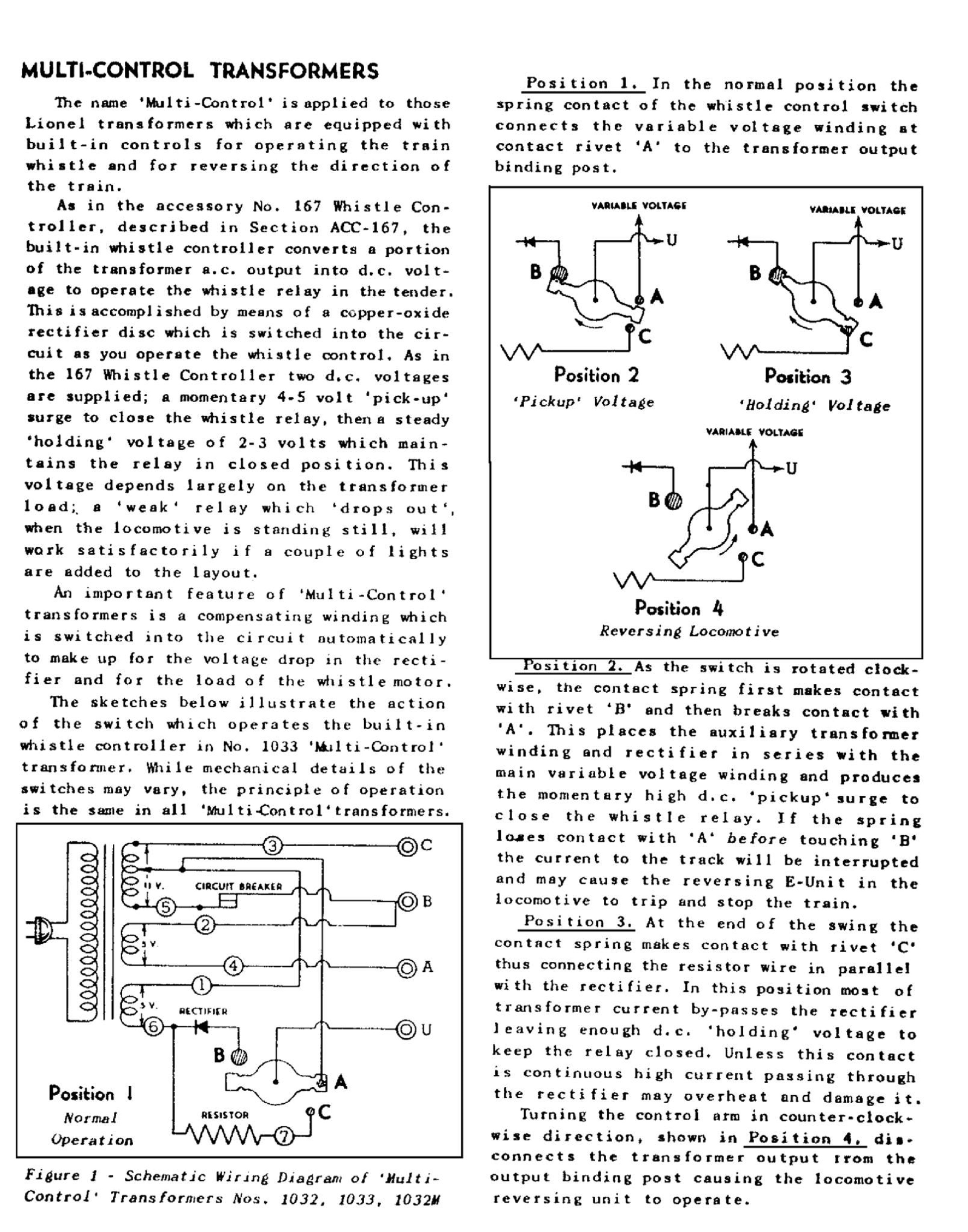
This is a very large image, open it in a new window to see large version.
So close… this is how it works from the factory… conventional(non-TMCC / non-command control) bell & whistle:
The BELL button toggles the BELL function on the circuit board, ie the BELL is ON until the next BELL button operation. When the whistle button is pushed this interrupts the BELL, and when the whistle is released the BELL will continue to operate until it IS disabled by the next BELL button operation.
Thank you Rob for the documentation and for your comments. I will improve my controller because there is no indication about the BELL function, ie the user does not know if the BELL is active or not. Of course I could add some LED but I want to keep the original box of ZW. So my BELL will be ON only for few seconds. The whistle does exactly the same as in your explanation.
(I would like to insert some pictures or videos but I have no idea how does it work in this Forum.)
A potential point of confusion I’m noticing is that there’s a lot of mention of a ZW transformer, and then mention of whistle and bell fucntions, and mentions of older Lionel trains
I don’t think anyone has clearly stated it here yet, but transformers with a “bell” button did not exist during the pre or postwar era! It wasn’t until the 80s or 90s at the earliest, afaik, that the ‘bell’ feature was introduced. If your transformer has a “bell” button, it is a more modern transformer. Lionel has offered multiple transformers over the years inspired by the classic ZW produced in the postwar years, which still feature the ZW identification, but include features and construction not original to the postwar (vintage) ZW.
Some pre and postwar models did have a bell- however, it was not activated by a transformer button! Rob already described how these worked:
If your ZW has a “bell” button, it is not a vintage ZW. All of the original ZW transformers Lionel sold had a pair of switches that were pushed forward to activate locomotive whistles/horns, and back to momentarily cut track power to trip Locomotive reversing units. They have corresponding labels that say “whistle” and “direction”.
More modern transformers now have a “whistle” and a “bell” button. These work how Rob describes them here:
[quote user=“ADCX Rob”]
the bell function is not dependent on the transformer, it is built-in to the bell function on the locomotive. The bell buttons are simply the reverse polarity of the whistle buttons and the first push turns on the bell, the second push turns it off. The whistle
Hi Elie
thank you for the comment. That means the toggle function for the bell is in the locomotive not in the ZW controller. Ie when I push the BELL button the impulse activates in the locomotive the BELL function relay ( bistable relay?) and this device remains in this status until the next BELL impulse comes from ZW.
This explains all my questions. Thank you! I will finish my project now and will place a short video on Youtube. ( I just wanted to be sure about the operation of the modern controller (ZW with all switches and buttons) and old controllers and make my unit compatible with vintage trains and probably also with modern models ( what I do not have).
Thanks to you and Rob for the help.
Eugen, yes, that is how it works- the ‘toggle’ happens inside the train, not the transformer. I do not know if the function is achieved with a relay or with solid state components, but I would suspect it’s all solid state.
-Ellie
Hi Ellie, thank you for the confirmation. From my point of view does not matter what is the toggle device inside of the train. The working principle was enough for my design. I do not know if I will have ever any train with BELL function.
[:)]