I have been perusing the old threads about lift up/swing out bridge accesses but I have yet to see a good way to power the track. Any ideas out there?
this is a thread on how I did mine
http://www.zealot.com/forum/showthread.php?t=154773
hope you find it useful
Bruce,
On my swing gate, I ran wires into the gate from the hinge side. Pretty straight ahead. For my lift, out I wired the track to a 1/4 phone jack with a short cord that plugs into the fascia after the bridge is set in place. Both work great although I have to plug in the liftout when the track power is off other wise I get a momentary (but annoying) short.
Guy
Threre’s an article in GREAT MODEL RAILROADS 2009, on how to do one. You could search the Index of Magazines on the MR home page to see where other articles are also. The one thing you want to remember is to have a fairly long section of track each side of the gate/liftout that shuts off when it is open so that no trains take a dive off or back off into oblivion.
Good luck,
Bruce, for a swing gate, you can hard-wire it in from the hinge side. Just make sure to use stranded wire, and leave enough slack so that there’s no strain on it with the gate either open or closed.
My layout has a simple lift-out at the doorway. I used a 5-pronged plug to provide power, mounting the female part on the layout facia, while the male counterpart is on a wire hanging below the lift-out section. Only four of the prongs are used for power - the fifth one ensures that there’s only one way to insert the plug into the receptacle. The wiring diagram below explains how to wire it so that the “safety sections” on either side are powered only when the plug is in place - these sections can be made as long as required. The two “connector sections” were included for a friend who wanted removeable sections so that there would be no rails sticking out from either side of the layout or from the lift-out. I built mine without these - the rails on the lift-out extend beyond both ends and align directly to the layout track. Because they’re so short, the connector sections, if you use them, shouldn’t need to be powered. The two wires (at the bottom of the diagram) from the side of the aisle where the receptacle is located run over the door frame to the "safety section on the opposite side.

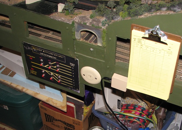
The lift-out, which is just a piece of 3/4" plywood, sits in brackets like the one shown here - the receptacle is the small round object just to the right of the bracket.

To keep everything properly aligned, I spiked the ties and rails as shown. I’ve had no problems with it in over 15 years of use.

Wayne
</
Mine is wired thusly: (I use brass barrel locks to hold the end of the bridge opposite from the two brass hinges on the other end)
-
feeder wire pair from command station to my PSX-AR because my swing-up bridge comprises part of a reversing loop. If yours is not part of a reversing loop, just run feeders from the closest part of the bus to the barrel locks holding the close end of the bridge.
-
output wires from the PSX-AR to the two hinges, one wire to each brass barrel lock. The bared end of one feeder wraps around one screw and the screw is then driven to anchor the portion of the barrel lock that ends up on the frame edge. Repeat for the other feeder wire, but to the other barrel lock. You choose whether it will be the bolt or the receiver mounted on the main frame. If you have no reversing to contend with, and no auto-reverser, it would be the same hook-up for feeders, but directly from the bus.
-
on the bridge frame, whichever portion of the barrel lock is mounted on it gets another bared feeder end wrapped around one of its screws and the screw is driven home.
-
the other end of the feeders just mentioned rise up through the bridge material and are soldered to the base of the rails along the bridge segment/frame. As soon as your bridge is locked into place, and power applied to the layout rails, the barrel locks will transmit power via themselves and the feeder pair to the rails. You’re in business.

I use modular jacks at either end of the bridge. The hinge side stays plugged in most of the time, although when I have to pull the bridge out for something, I just have to unplug it. At the other end I use the barrel bolt with a couple more jacks. The 8 pin cable carries the DCC control bus, and a 4-wire phone jack for track power.

Hope this is useful.
Lee
From the answers the majority do not use a swing gate. They use a lift out or drop section. If you truely want a swing gate (movement horizontal) I would take the following approach. I would make a substantial Triangular or box frame to prevent sagging and attach it to the railroad with substantial hinging. I would wire one rail with a flexible wire. The other rail I would isolate far enough onto either side of the layout so that any train had sufficient stopping distance in either direction and cut that rail. This rail would also be wired but the stopping mechanism would be a push button mounted so that it is made by the swing section when closed and opens when the swing section is open. This would automatically prevent power to one rail when not in place. i would also use a pulley and a weight so the swing section would automatically allign itself in the closed position.