This topic has been discussed multiple times before. I am raising it again specifically to answer questions asked by Lee (kasskaboose) that he sent me in a PM. I decided to answer here rather than in a PM so that others can share their knowledge, and others can learn.
Here is his question:
Hello,
Thanks for your help earlier with my LED Qs. Can you pls help me with adding interior lights to some HO-scale buildings? I have some Yeloglo white LEDs but I wasn’t sure how to use them on a DCC layout? What do I need to purchase to control the lighting? I understand that my old DC controller might not work.
Another route is using a strip of LEDs, but again, how to control the lighting?
There are a ton of vides but none tell you what to purchase without making the process too cumbersome and expensive.
Thanks.
Lee
Before the wiring starts, the first thing that should be done is to seal the building from light leaks. Plastic buildings may glow in the dark like they are radioactive, and other buildings may have light leaks at the corners. The easiest way to
There are a variety of ways to control the lighting, ranging from a simple off/on switch to DCC stationary decoders to Arduino modules. It depends how fancy you want to get with special effects.
Since this is your first attempt I’m going to suggest that you use plain old off/on toggle switches. They are available for peanuts on eBay. You can use one switch to control the whole thing (be aware of the amperage rating of the switch. Use the same 75% rule as you did for the power supply). You can make things more interesting by using several switches (and more wire) to control individual lights or sets of lights. For example, you could wire a residential house on two circuits with each controlling lights in different rooms so that you can mimic activity in the house. You might want to wire your street lights separately from the building lights so that the building interiors can be seen during the day when the street lights would normally be off.
Another option is to use DCC stationary decoders. I think that is self explanatory. However, personally I want my DCC throttle to just control trains. I don’t want to be distracted by trying to remember umpteen stationary decoder numbers while I am trying to run trains.
Arduino control is something worth exploring if you have any electronics capability. There are ton’s of opportunities. One of the neatest is to set up random lighting sequences in your buildings so lights are going off and on all the time.
I said I would talk about LED strip lighting. It is actually very little different from using single LEDs except you don’t need to worry about resistors. LED strip lights already have the resistors built into the system. You have to observe the same rules about maximum amperage. You may find that LED strip lights are very bright, and you usually have to use them
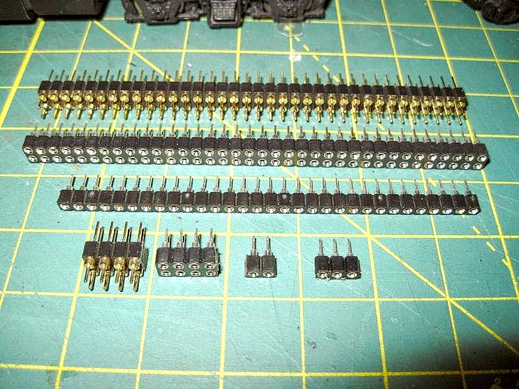
I need an explanation of how mini plugs like this work. I can see how to break off the pins to make a two pin plug. But what is the arrangement for attaching wires to the pins? How do you separate the strip into a male plug and a female plug?
Pretty certain once I see it I’ll say, “Man, I could have figured that out.” But better safe than sorry.
In this day and age there is a lot of confusion about male and female. [}:)]Header sockets and pins are not yet woke.
The strip pictured in the link is cisgender,[:D] in this case female. The protruding metal bit is what you solder to. You will also need cisgender male header sockets, both genders are pictured here
One end of the male end is what you solder to, the other end is the business end.
I suggest scoring both sides of the strip when you break them into smaller pieces, otherwise the plastic has a tendency to fracture.
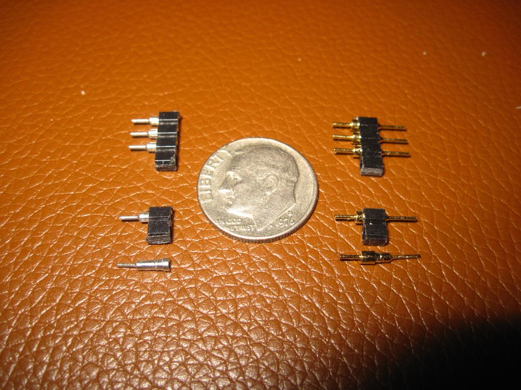
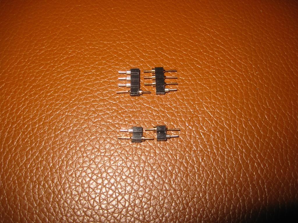
The strip contains both the male parts and the female parts. Let’s say you want to make a two pin connector. You would cut two pins off of the strip to form the male half of the connector with the pins being the part that go into the female plug. Then you would cut two more pins off to make the female connector. The pins on the male connector plug go into the holes on the female connector to make up the plug. They hold quite tightly and make good connections.
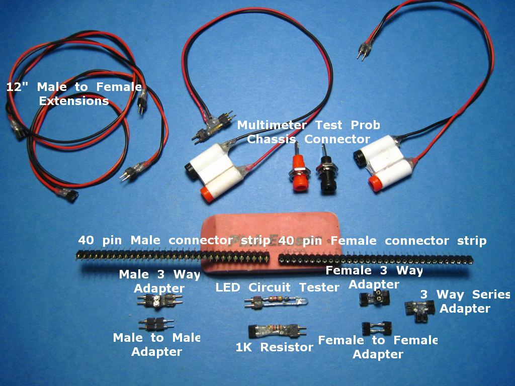
Since my answers are always too long anyhow, I will add in some suggestions on how to make up the plugs:
Soldering is a bit finicky. You will need a pencil tip soldering iron. Wires are attached to the pins on the female plug, and soldered into the holes on the male plug.
Hold each plug in a vise (or a pair of pliers with an elastic around the handles).
Apply a tiny amount of solder flux (non acid) to the wires and the plugs where the solder will go.
Tin the wires. If you don’t bother to tin the wires I can guarrantee that you will be frustrated!
Hold the wires tight to the pins on the female plug and touch the tip of the iron to the wire and pin at the same time. The joint should be smooth and fairly shiny. If it looks crusty or dull, apply the heat again and make sure you don’t move the wire until the solder is hard. It helps to have a bit of extra solder on the tip.
For the male plug, insert the tinned wires into the holes on the plug, get a tiny bit of extra solder on the tip of your iron, and then touch the tip to the wire and the lip of the socket at the same time. The extra solder on the tip should flow into the hole almost immediately.
What a fantastic set of answers. The questions I and others ask require a level of knowledge and an ability to explain technical issues in a clear way. This is far from easy, but I am convinced that with enough interest, we’d get a great set of answers.
If you’re just looking for a simple way to provide lighting in buildings, then check out the Dwarvin system.
Dwarvin also sells lamps, signals, detector units and other accessories for different scales. It’s a little pricey at first, but I’ve been happy with its performance the two years I’ve had it.