Hello everyone, can some of you guys recommend the best way to control hard to reach turnouts without having to add a slow mo machine etc? Right now financially i am not able to go the DCC route with my turnouts and need some way to be able to control several hard to reach turnouts on the back side of my layout. I have read various articles on using everything from piano wire to metal rods but i have never really understood how this works. If any of you have any links on how to best do this please post them here so i can see how to do this…Many thanks!
Think bicycle cable brakes. That should work. Personally I’d save up a get a few switch machines for the hardest to reach. Maybe search eBay for some bargains. Would save a lot of trouble
have you considered using a tortoise machine? you will also need a 12VDC power supply and a DPDT switch
i would suggest a RC airplane style pushrod, but additional linkage is needed, as well as a way to hold it in on of two positions.
You can get older style switch machines for cheap on e-bay. Would have sent you a box of them but they have been e-bayed early this year.
I could be mistaken, but I think the OP was born in this century and “Cheap” means something different to him that to some of us with more substantial incomes.
Blue point switch machines really aren’t any cheaper than tortoises but this video may help you see how RC cables could be used
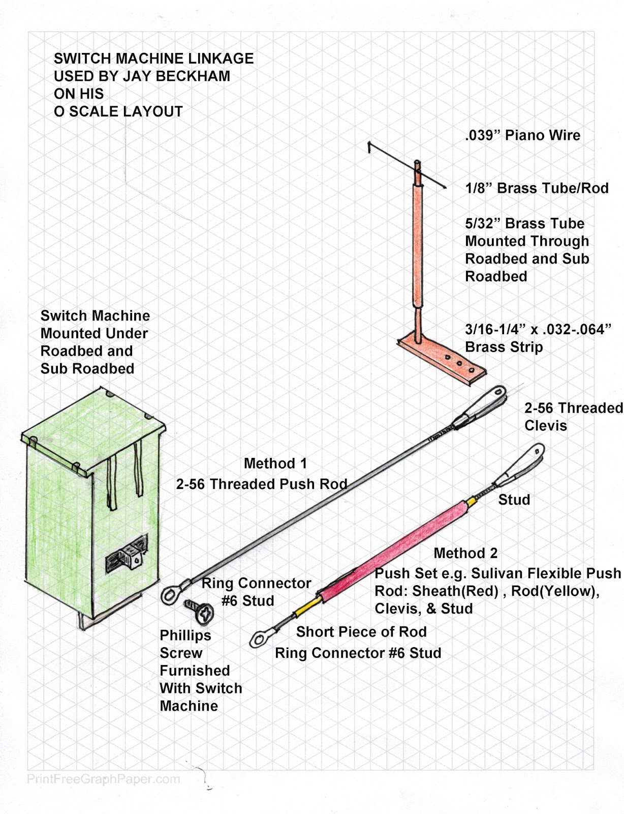
Somewhere on this forum was a picture of turnout linked to a piece of piano wire, that ran through a brass tube, slightly below the surface of the layout. The piano reemerged into a Caboose Hobbies ground throw.
DIY servos would be cheap. I use 2" foam and I haven’t figured out how to use the with that thickness.
For years I have been using 1/8" copper coated welding rod from welder supply stores for almost all of my turnouts. I don’t like the idea of reaching in, ALL turnouts are controlled from the edge of the layout. They’re so cheap it’s almost embarrassing, but super reliable. I have one that reaches from the panel to a switch about 7 feet (the layout is not that deep, this runs parallel along the benchwork).
They all include a dpdt slide switch to keep tension on the switch points and power the frogs.
If you want to see them, I’ll post a how-to later. Dan
You need a slightly different control if the turnout has no points spring.
Peco and Micro Engineering need only a rod or constant length cable (Bowden type which is the wire inside a stiffer but still flexible sheath described as bicycle brake cable).
Atlas turnouts have no internal spring to hold the point rails against the stock rails so your rod or cable connection must also have a device to hold the rod or cable, or the point rails directly in place. Some kind of spring on the control rod or wire would work, obviously.
Servo motors do that by applying a constant voltage to the motor. Manual switch stands are usually some type of over centre lever. For remote manual operation you could fit the over centre lever at the hand end rather than the turnout end.
The forces are very, very low but so is the throw distance. With spring loaded point rails precision in the length of the throw of the hand control is not so important. With free moving point rails your hand operating device needs to maintain constant length very accurately.
This is why the electric turnout control motor was invented…
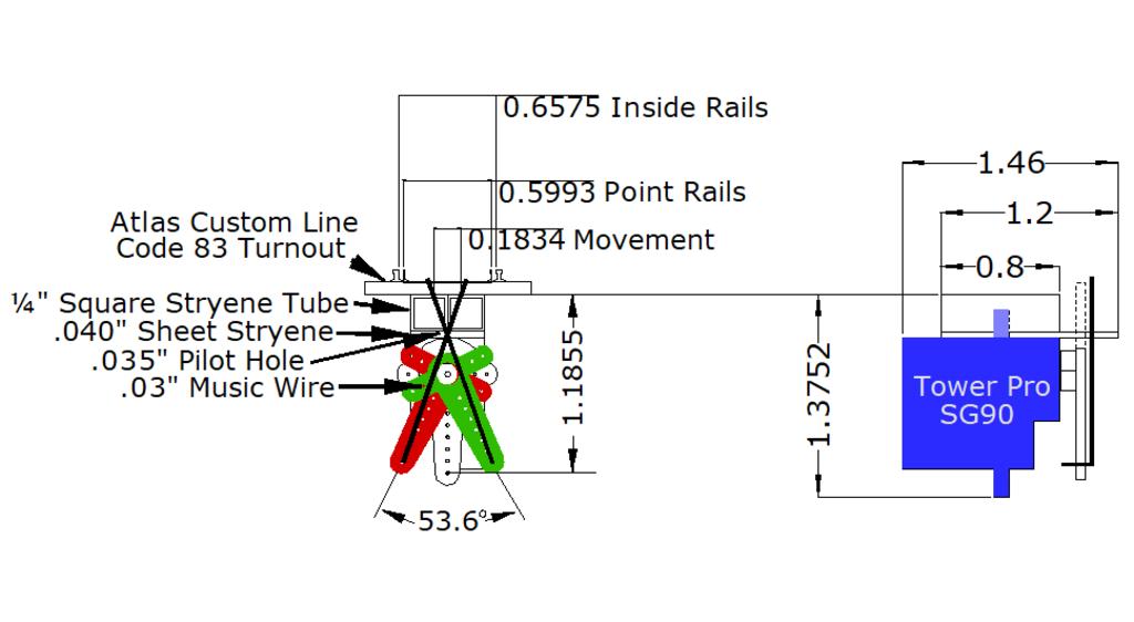
You might try a mini Tower Pro S90 Servo (eBay from China under $2 ea US under $4 ea).
https://www.ebay.com/sch/i.html?_from=R40&_nkw=sg90+servo&_sacat=0&_fsrp=1&LH_BIN=1&_sop=12
I bought a bunch off eBay (China) that I figure were Clones and not the real Tower Pros. The Clones heat up at a continuous 50ma.
The real Tower Pro servo motor will operate in stall mode without heating up using a resistor in series with the motor limiting the motor to a max of 50ma to 55ma.
The only turnout I have used with a servo is a Atlas Custom Line #6.
I have not done this as a permanent installation, only experimental on my workbench. I do have one installed on my layout for testing and so far it has worked very good.
You have to open up the servo and remove the wires to the motor and reconnect two of the external wires direct to the motor.
This is the mount I made for a servo that seems to work very good on the workbench.
Mel

My Model Railroad
http://melvineperry.blogspot.com/
Bakersfield, California
I’m beginning to realize that aging is not for wimps.
Thank you guys for all the suggestions, i apologize for not including the details of the turnouts i am using etc…I am using Peco #8 turnouts and my benchwork is 2" foam board…Thanks again, i am looking into some of your suggestions…![]()
https://www.handlaidtrack.com/bullfrogs
https://www.handlaidtrack.com/bullfrog-switch-machine-videos
Terry
Hello All,
As has been posted, PECO turnouts have a retention spring that will hold the points in place.
A length of metal or styrene tube imbedded in the 2-inch foam board with a piece of stiff wire, AKA “Piano Wire” bent at one end into the hole in the center of the throw bar will work. You might need to expand the hole in the throw bar to fit the wire.
The guide tube should be just slightly larger than the wire to avoid unnecessary play in the assembly.
You can fashion or finish the other end as you wish- -the most inexpensive would be to bend the end into an “L” or triangular shape for grip.
Some folks have used wooden knobs or small pieces of dowel as handles too.
You can color code the handles; paint the wooden knobs or use colored electrical tape, and use a matching color (fingernail polish works well) to color the ends of the throw bar(s).
Hope this helps.
My last layout has 4" of foam, servos worked just fine. Drill a hole under the throwbar, just like for a Tortoise. No different than with any other material or thickness, really. .039 wire was plenty sturdy enough to put plenty of force on an Atlas throwbar and move it and keep the points pressed against the stock rail.
They even make drill bits long enough for that - they are often used for drilling holes through studs and wall headers for wiring.
–Randy
I have used unbent wire coat-hangers and am currently using 3/8" round wooden dowels at the bottom end of a pivoting length of lath or strapping. I even use cut up wooden paint stirring paddles, the give-aways at the local hardware.
The wooden dowel’s proximal end emerges from a hole in the fascia to be grasped by the operator. To prevent it from being knocked about, I glue a small wooden block right beside the hole, and I paint the adjacent face of the block with some indication markings. The end of the dowel projecting from the fascia gets small bands of contrasting colours such that when the points are ‘through’ or diverging, the band’s placement compared to the protection block’s marks gives me an indication of where the points are.
I have a #6 double slip whose points need something a bit firmer, so my intent is to use a threaded metal rod to the bottom of a lever going up to the throwbars. The operator’s end of the rod will have a knurled knob, also threaded, and the knob will be retained inside some kind of a block to prevent it from moving back and forth. The idea is to keep the knob in one place, but the threaded rod will move back and forth to actuate the lever rising up to the throwbars.
The Bowden cable I was going to use for switch activation in the early 1970s was then called ‘choke cable’ and was likely cheaper than bicycle brake cable. I have no idea how easy or cheaply this can be found in a largely post-manual-carb-choke world.
That product used a long helical spring as the ‘sheath’ that guided the wire inside. If lubrication and protection from environment is not needed, this ‘spring’ could be formed open, with fewer turns to the inch, and still guide better than a few sections of rigid tube guides with bellcranks between.
I’d rig the switch machines with a spring to ‘snap’ the points from one position to the other, and have the cable arrangement toggle that spring, instead of just moving the points with direct connection (and then relying on positive retention of the linkage to hold point position without damage, etc.)
If you cannot easily reach the turnouts and you cannot afford switch machines, then the only option available to you seems to be push/pull rods accessible at the fascia.
Not that you want to hear this, but if you cannot easily reach the turnouts and you cannot afford switch machines, then why not just redesign the layout to avoid hard to reach turnouts. That makes the most sense to me.
Rich
Bowden cables are designed for push forces. Close tolerances between cable and sheath are required if the throw distance at the business end is small, as it is for HO turnouts. My guess is a Bowden cable might be as expensive to install as a motorized solution. The difficult part would be locating cables of approximately the correct length.
An easier answer may be to install two pull wires on some sort of centre pivot lever as for a Watts linkage but flexible in the push direction. The wires could be located through one set of eyebolts or similar. Two operating levers might be easiest to design and rig at the hand end or connect the wire ends above and below the lever pivot.
Several car makers use twin Bowden cables in this manner to create a very precise shifter linkage for those who still think manual shift gearboxes are a good idea.
Prototype point controls used manually operated rod systems for a long time. I’m not sure if any used pull/pull wires.
How many of these do you have to do? If it’s only one or two, you will probably save time and aggravation by just biting the bullet and installing switch machines. There’s a learning curve to building linkages, and perhaps even some tools and materials you don’t have.
Again, depending on the configuration, have you thought of replacing the Peco with something cheaper, like an Atlas Snap-switch? Save the Peco for a later project. This could work fine if the turnout isn’t too visible, and the normal routing is on the straight path, with the divergent path used for a low-speed siding or something similar.
Can you easily get to this turnout now to work on it? Is the track already paid and ballasted down? This could be another complication.
This simple method using 0.047" steel music wire and a wooden knob on the fascia is tried and true for Peco turnouts and costs less than $1.00!
Long installations could require 20 cent eye screws to support the music wire.

-Kevin
I am still building my HO layout. I have 32 turnouts and counting. I use a cheap 3-way light switch mounted beneath the turnout. This allows you to wire the turnout so that the frog’s polarity is switched when you flip the turnout. You control this thru the use of dowel rods or metal rods that connect to a push/pull knob on the fascia. (I have been using the dowel rods so far). This method is shown in great detail in an article by Mike Evans in the November 2013 issue of Model Railroader. I have been using this system for 9 years and have no complaints. Buying the cheapest 110v 3-way switches, cheap blue boxes for mounting, dowel rods and some piano wire to connect the dowel rod to the switch and the switch to the turnout, my investment is less than $8.00 per turnout. I think you might also be able to find this info on youtube or even in previous posts on this forum. I woulld be happy to answer any questions you might have about this method.
wdcrvr
IRC Atlas turnouts usually come with a ‘surface-type’ switch machine and a control switch. I have converted these surface machines to under table machines and used them on my BRVRR layout for more than 15-years with only one failure.
There is a short how-to on my website on how to convert them. Here is the link:
Good luck.