I recently realized that I needed to change the layout of my steam locomotive service facilities. What I need to know is what the typical arrangement was for the water tower, coal tower, oil bunker, sand station and the ash pit? Were they all on the same track? If so, in what order? If I should have more than one track, what goes where? This will be a small(er) service facility so it will only be servicing one or two steam engines at a time.
I’m modelling the transition era so there will also be diesel refueling facilities as well, but obviously they will be on a different track. I’m going to try to fit a wash station somewhere in there too.
Thanks as always folks. I really appreciate being able to use the forums to answer my many questions.
To answer your question about order: I think it varies from terminal track facility to terminal track facility. However, having a separate steam and diesel terminal tracks is a logical assumption.
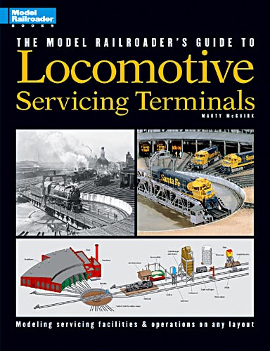
Unfortunately, I have it boxed up but Marty McGuirk wrote an excellent book put out by Kalmbach called The Model Railroader’s Guide to Locomotive Servicing Terminals:
It covers but steam and diesel facilities - large and small - and shows how they evolved over time. If your LHS doesn’t have it in stock, Kalmbach has it for 50% off. It’s definitely worth purchasing and will answer a number of your questions.
First and the most critcal element Is the topography. I have never seen a master layout from any railroad. It is based on what type and dimensions of the space available.
Have you looked at CPR’s Orangeville, Ontario facility? It isn’t too far from your location. They had more than two steamers based there, yet their facilities were not as extensive as those you are considering.
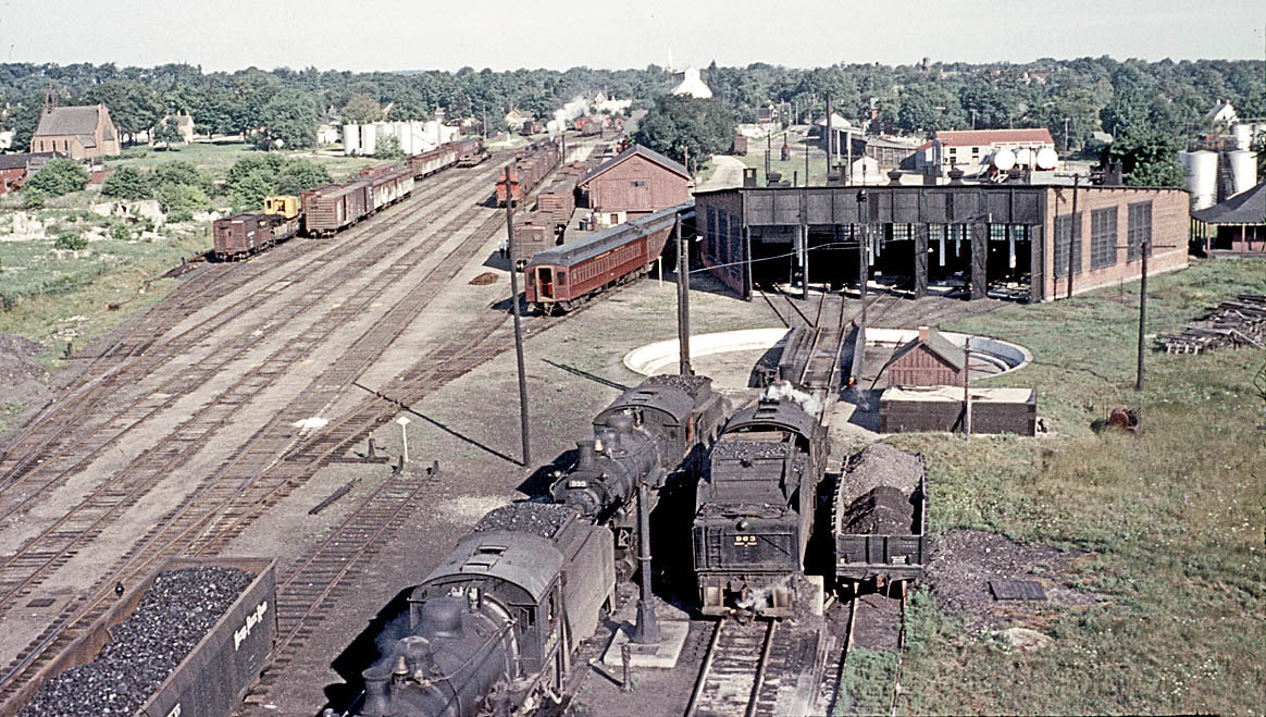
This 1956 photo appears to be a telephoto shot taken from atop the coaling station, which was located on the main just before the yard throat. Water appears to have been taken from standpipes. AFAIK, there was nothing much else.
I really like that NKP hopper of coal over on the lower left.
Besides the water supply (note that it can supply both incoming and outgoing tracks), there’s an ash dump below the incoming loco. Note the bit of concrete wall for the pit showing. From the way the ashes are piled in the gon, it looks to me like they use a small crane to clear the dump. And over on the far left track on the other side of the main is what looks like a perfectly good crane! How interesting.
Over near the tracks to the table, it surely looks like a box of sand (note “spillage”). I do see what looks to be a ladder leaning up against the building. I expect sand was loaded into the sand dome by hand up the ladder. The building would likely be a drying shed, especially considering the sand box is open to the rain.
Marty’s book looks like a fun and informative read even if yer not planning a facility.
The ash gon does look to be on a depressed track. But it only looks a couple of feet down. So they’d still be tossing those ashes awfully high in the air to get over the sides. I feel that the neat piling in the gon was done by a clam-bucket.
That said, a person COULD have a lower track and tell the guys to wear a mask when the wind is bad.
I understand that there wasn’t a ‘Master Plan’ for the service facilities. What I was really trying to understand is what would the logical order be for the individual components/activities. In other words, when a steam engine came in for service, what did they do first, second, at the same time? Did they drop the ashes first, fill the coal hopper first, water tower, sand tower… or did it not matter that much?
Dave,No book will give you the correct answer because of the varibles between locations based on the available space and the railroads needs. I’ve seen photos of ash pits before the coal tower and just before the turntable.
There is no need to add worries where there never was any.I suggest studying photos of smaller engine service areas and find the one that suits your needs…
And as that NKP gon shows loaded hopper cars did indeed leave the home rails unlike some “experts” would lead you to believe.
The book will likely answer all your questions. But you don’t have it yet, so I’ll anticipate a bit.
You use the phrase “came in for service”. Well, it depends on what kind of service. And the amount of time there is to do it. Or NOT do it.
At the end of a run, an engineer will report verbally or in writing (depending on how formal things are on the RR) any irregularities. That information will be forwarded to what I’ll call the “engine manager”. He’ll add that to his already collected information of that loco and combine it with what I’ll call the “demand factor” (sorta self explanatory). Then he’ll decide what to do with the loco.
If there’s a place for it and the time, he’ll surely dump the ashes. He may then simply top up the water and coal and place the loco on the ready track. On the other hand, the loco may need maintenance. Then it likely goes to the roundhouse (after dumping ashes). The fire may be put out or it may be maintained, depending on the type of maintenance. When the loco is subsequently in good order, it may either stay in the roundhouse or be sent out to the ready track, depending on demand. Coal and water are usually added just before going to the ready track. One r
I said earlier that the coaling tower was on the main. That needs to be corrected. It was on the main, but destroyed by fire about ten years before this particular photo was taken. The new tower was built on its own track adjacent to the main.
First every engineer is required to fill out a engineer’s locomotive mechanical report at the end of his run and that is forward to the mechanical department.He is also required to fill out a pretrip inspection report.
Here why.Should old #344 be in a wreck the FRA will inspect the mechanical records as a matter of course and there is no “Well,nobody told me” or the engineer’s “I reported it” excuses. Its all there in writing.
As far as deferred locomotive maintenance there’s very little of that allow under FRA rules concerning locomotive maintenance. Some things can dead line a locomotive including crack glass.
There are thousands of variables when it comes to servicing areas on railroads for any one book to cover.Studying pictures in Trains or Classic Trains is a start as is railroad historical photo sites.
Interesting. I would assume that, since the old one was on the main, it supplied coal to tenders on the mainline tracks. I wonder if it also supplied coal to the enginehouse yard trackage.
Conversely, if the new tower was placed over the yard trackage, I wonder if there was a coal chute on the side to still service a main track.
One reason I can think of for rebuilding the tower in a new location would be that, should another fire happen, the burned hulk wouldn’t be blocking the tracks. As it was doing about the time the rebuilding decision was made.
Another is that there’d be less “stuff” above the mainline track. Sometimes “stuff” inserts itself downwards and causes trouble for approaching trains.
Still another is that reconstruction could start right away, before the old remnants (and perhaps the foundation) could be removed. This especially if they didn’t choose to rebuild “in kind”.
That is just a FASCINATING picture. So much better than just another 3/4 front shot of a steam locomotive. And in COLOR!
Take the roundhouse, fer example. First off, it’s empty. Now, I don’t know WHY that I find that interesting. I just do.
But, moving on, since it IS empty, you can see how they painted the interior: a dark color up maybe 4’, and the rest white. And notice the smoke jacks. They’re different. Get’s me thinking that one set was added later. I’ll remind you that with this setup, you can ha
The main reason it was metal was dismantleability (if that is a word). When the CPR had it built, management new that steam would be out in the not too distant future.
They wanted something that would come down with relative ease, which is why they didn’t go the typical concrete route.
Did somebody have insomnia? Here’s a few teaser pages but I have a link to Photobucket where you can see the rest and zoom in to see the details more clearly. I hope the pages are legible.
Ed,What you see in that book is large serving areas more suited for a club or a basemment filling layout.
How about the more compact servicing areas that was in cramp spaces? A branch line or a yard in a small city wouldn’t have a smaller servicing area since there may be two or three local crews working out of that yard. There may not even been a engine house.
Oh, yeah, I agree Brakie. The second set of pages from the ICS book is geared toward a smaller (but still big for model RR purposes!) operation.
Those were the examples I had on hand and they explain the “turn-around” of a locomotive, now, like we all have to do, is figure out what has to get chopped off to fit on our tiny layouts.
I just figured Dave and anyone else might want to read… and keep reading. In his original post Dave was asking about the arrangement of the facility and the routine for the engine service. Both those articles hit on that.
There’s lots more pages I left out devoted to HUGE backshops, like Altoona or Topeka but that’s way more than what we can possibly model.