does anyone know how a valve gear (e.g. Wlaschaets) was designed for a particular locomotive, determining the length of all the linakages to obtain the desired travel distances and timing?
did they build scale models to test on? Was the design simply copied from one loco to another? were there adjustments that could be made on the loco? was a design ever modified after testing on a prototype to improve performance?
The early development of steam engines was as much trial and error as it was purposely designed. No one really knew what they were getting into in the early days. There was no real way to model the performance improvement of a new idea without actually building it. Calculatiosn could show things like how much time the valve would be open and how much motion there would be, but at the same time as valve gear was being improved, the boilers were being improved as well so you had higher steam prssure also affecting the output power and efficiency.
There used to be a neat program that showed all sorts of valve gear in motion and you could adjust the cutoff to see how it all worked - it even modeled the steam. Besides all the various slide and piston valve options, it also had some of the rotary valved designs like Franklin and Caprotti.
There is no quick answer. The study of valve motion fills dozens of books on the subject and to post all of them here would require a major undertaking.
Suffice to say that the railroads and the locomotive builders working together probably employed more engineering staff than any other industry in the first half of the twentieth century. There was a constant push to get every degree of heat out of the fuel and turn it into tractive force/speed.
I’ll post a few excerpts from several of the books I have on the subject. I highly recommend having some of these reference materials in your own library which will aid immensely in satisfying your curioscity on the subject.
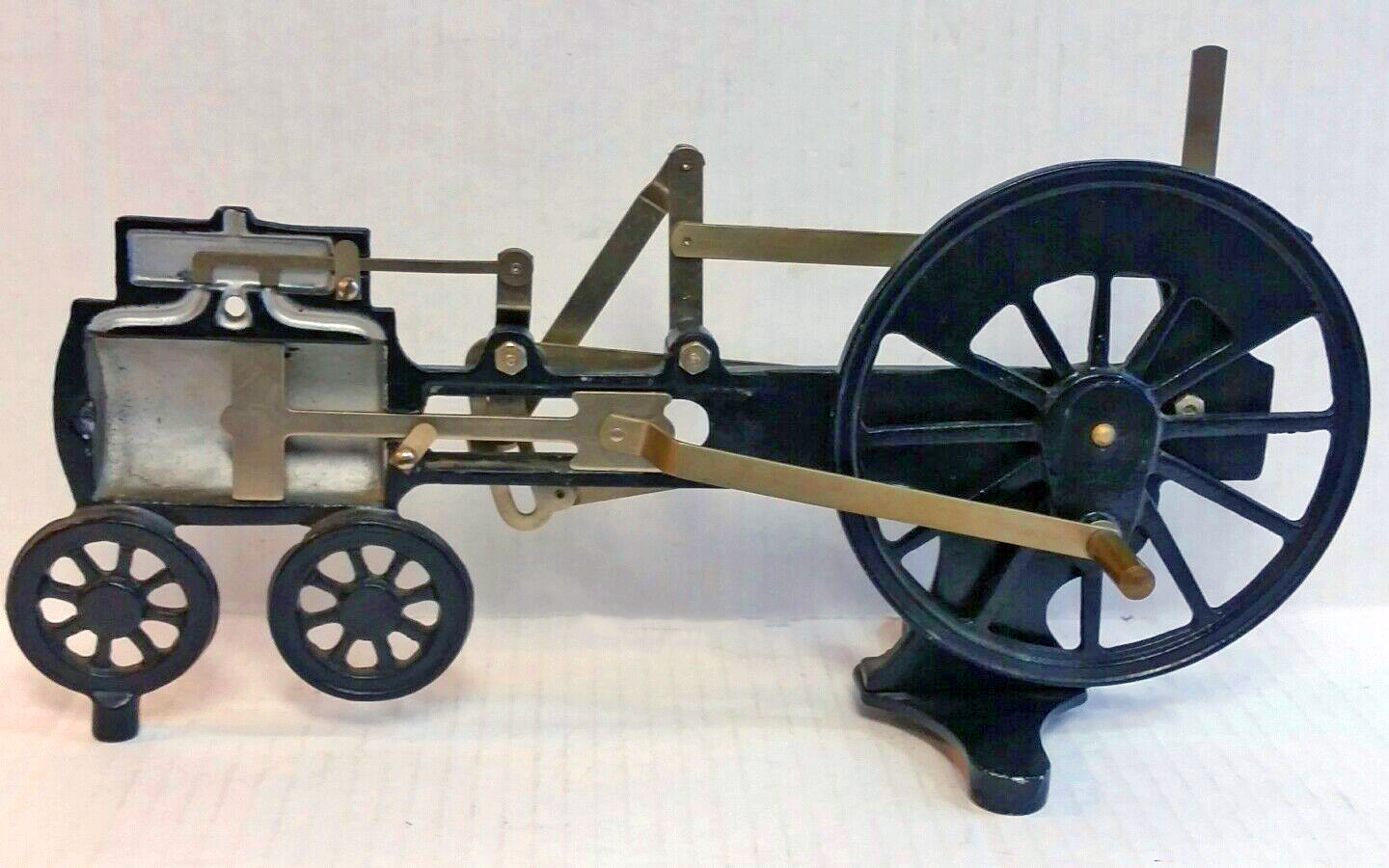
so in 1844, when Walschaerts had the idea for outside valve gear, don’t you think the tried it out on a small static engine in the shop?
seems like a scaled static engine would be handy as they work out concepts, basic design and dimensions and then later try improvements.
how to the live steam guys do it? are they just scaled down engines?
i read in Bruce, that the Phily & Reading (?) tried the Walschaerts valve gear when the axle broke on a triple cyclinder Stephenson valve gear locomotive. Results were so good, they never looks at Stephenson again.
My (un)educated guess would be it would be more work to take the time with small precision tools and such to build a small working steam engine to try it out on than it would be just to go apply it to a real engine and see how it works. It’s true that (at least in the US) you had to build a model of an invention to get it patented, but the model didn’t have to be a working model per se - so for something like a new type of valve gear, the models parts would all move like the real one to show the motion and settings, but it wouldn’t be designed to actually work under steam. Most likely the parts would have been made of wood and made to just move manually to demonstrate how the device works.
thanks for posting the images from Edmund. They look interesting
the need for corrections suggests everything is theoretical until the first in a series of engines (e.g. RDG T1) is built and corrections are made both because of difference in the actual engine and plans, and because of errors in the valve gear dimensions/design.
i assume that since every engine in a series may be slightly different, corrections to each engine are unique.
i assume that the valve gear design is reused from one engine series to another, with perhaps minor modifications based on experience.
still curious how the first prototype of the Walschaerts valve gear was developed
I think for the locomotive builders adding the valve gear components was pretty routine. It’s basic math based on things like the size and spacing of the drivers and side rods etc. Once the valve gear is in place and has been set up, the engineer controls the valve gear from the cab, so can make tiny adjustments to make the engine work at it’s most efficient.
Vernon Smith’s book “One Man’s Locomotives” has a chapter on his involvement with developing the Poppet valve gear, that might give you some insight into the process??
That’s a good point. Math can tell you the maximum allowed valve movement in the full forward and full reverse positions. Anything in between is adjustable on the fly. Performance data once the loco was built was obtained through empirical testing. Previous version of the loco, was able to pull X cars on the ruling grade and maintain a track speed of Y miles per hour, while using C tons of coal and W gallons of water. Pull the same train with the new design, see how it does in respect to ability to maintain speed and consumption of coal and water. Later on, dynomometer cars were developed to make the comparisons a lot more accurate than “they both pulled a 40 car train, with a mix of loads and empties”.
yes, once the design engineer has made modification unique to the locomotive.
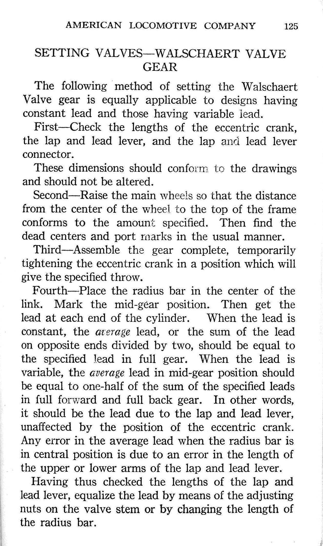
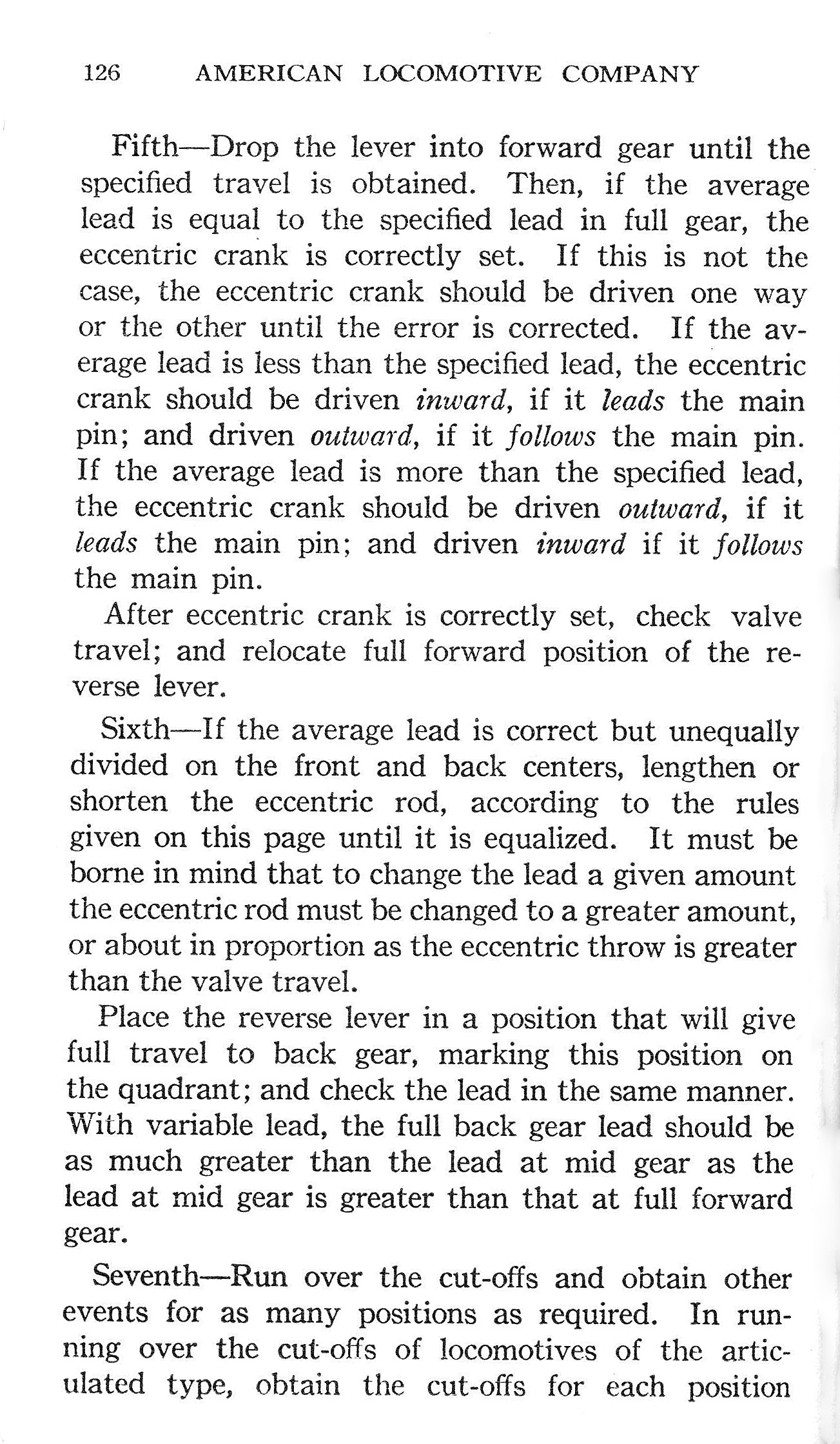
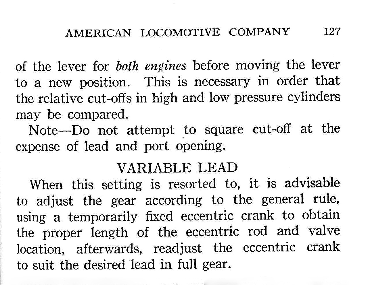
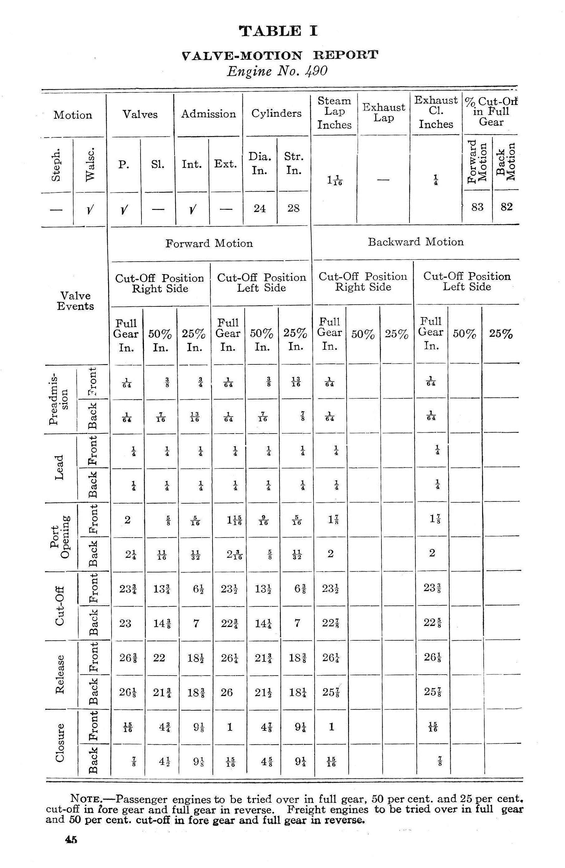
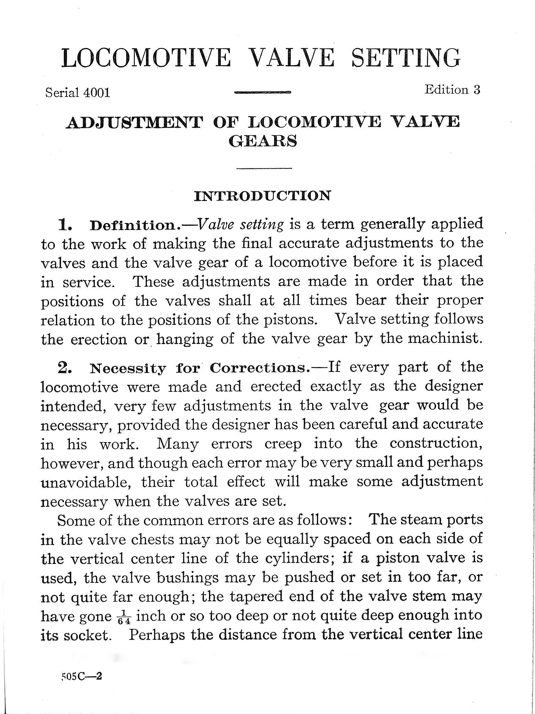
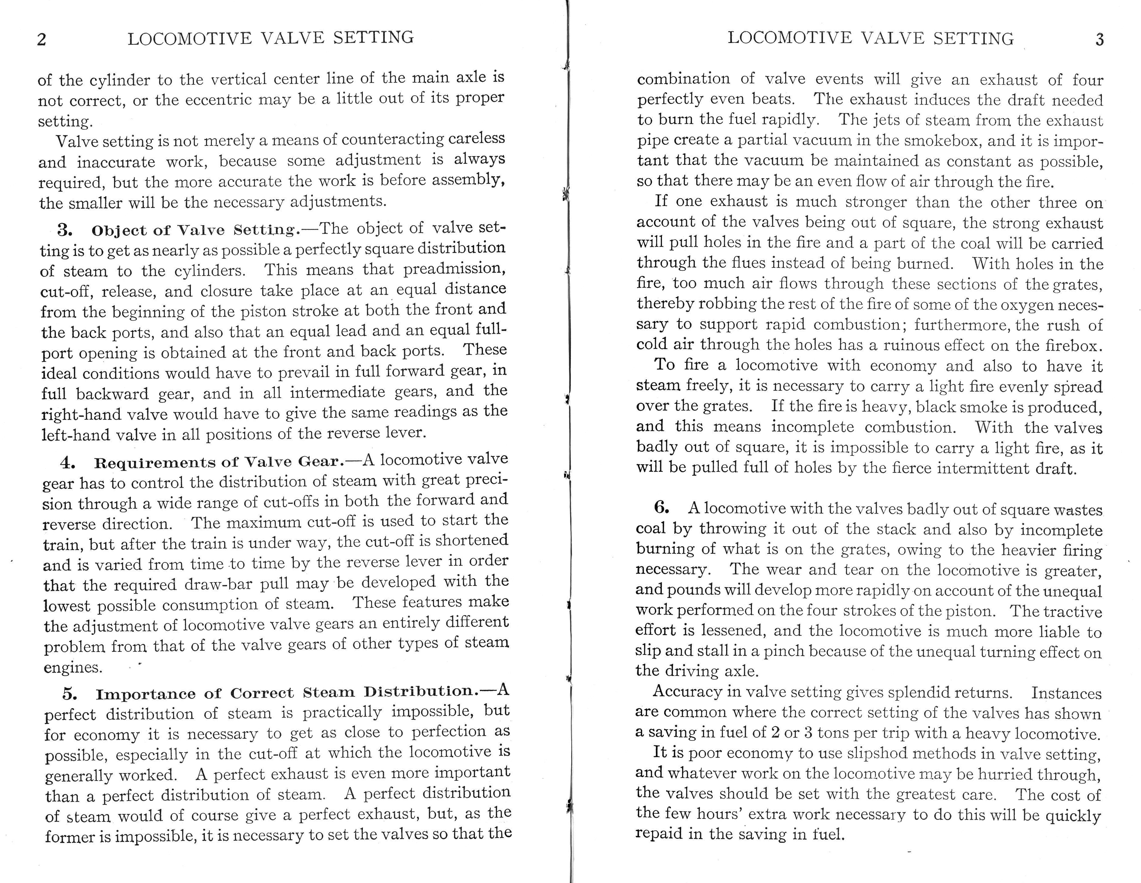
the notes Ed posted on Edmund describe obtaining a “square distribution of steam to the cyclinders” due to a host of manufacturing and assembly issues and well worth “the cost of a few hours extra work” “saving in fuel 2 or 3 tons per trip with a heavy locomotive”.
you want the piston performance to be identical in both directions and for both pistons.
i think by “square distribution” (see pg 2, sect 3) they mean the that the valve timing is the same in both directions, symetrical. this means that the valve is open for admission and release the same duration in both directions. achieved through measurement of distances on the valve gear, not pressure or force.
I guess this means performance will not be the same in both directions.
It also means that the exhaust “chuffs” (for lack of a better term) are timed at exactly 90° per revolution of the wheel.
Engines that are “out of square” sound like they are limping or shuffling with an off-beat exhaust.
I have some Broadway Limited Paragon 3 decoders that — I believe — they were trying to get a little off-cadence exhaust sound and, to me anyway, the result is not very pleasing, especially after the effect wears thin, say after a minute or so.
Impossible. There’s a piston rod with a cross section of about 10 square inches or so on the aft face, and the rod must take up some of the volume that steam would occupy on the ‘free’ side of the piston, the for’ard face.
Warning, I am about to go full mechanical engineering student on ya’ll…
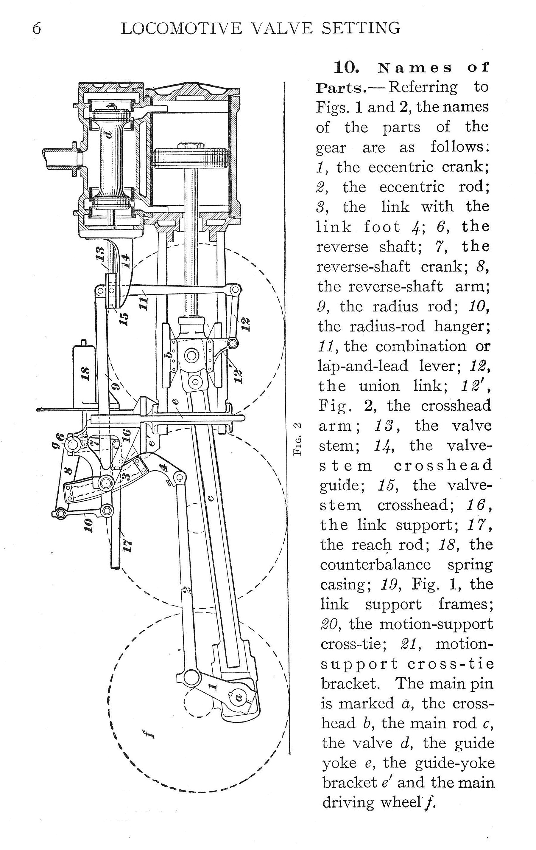
Valve gear are based on the four bar linkage methods, a basic engineering concept still taught today. Most valve gear designs appear to mimic a basic linkage design most likely some sort of Crank-Rocker variation perhaps:
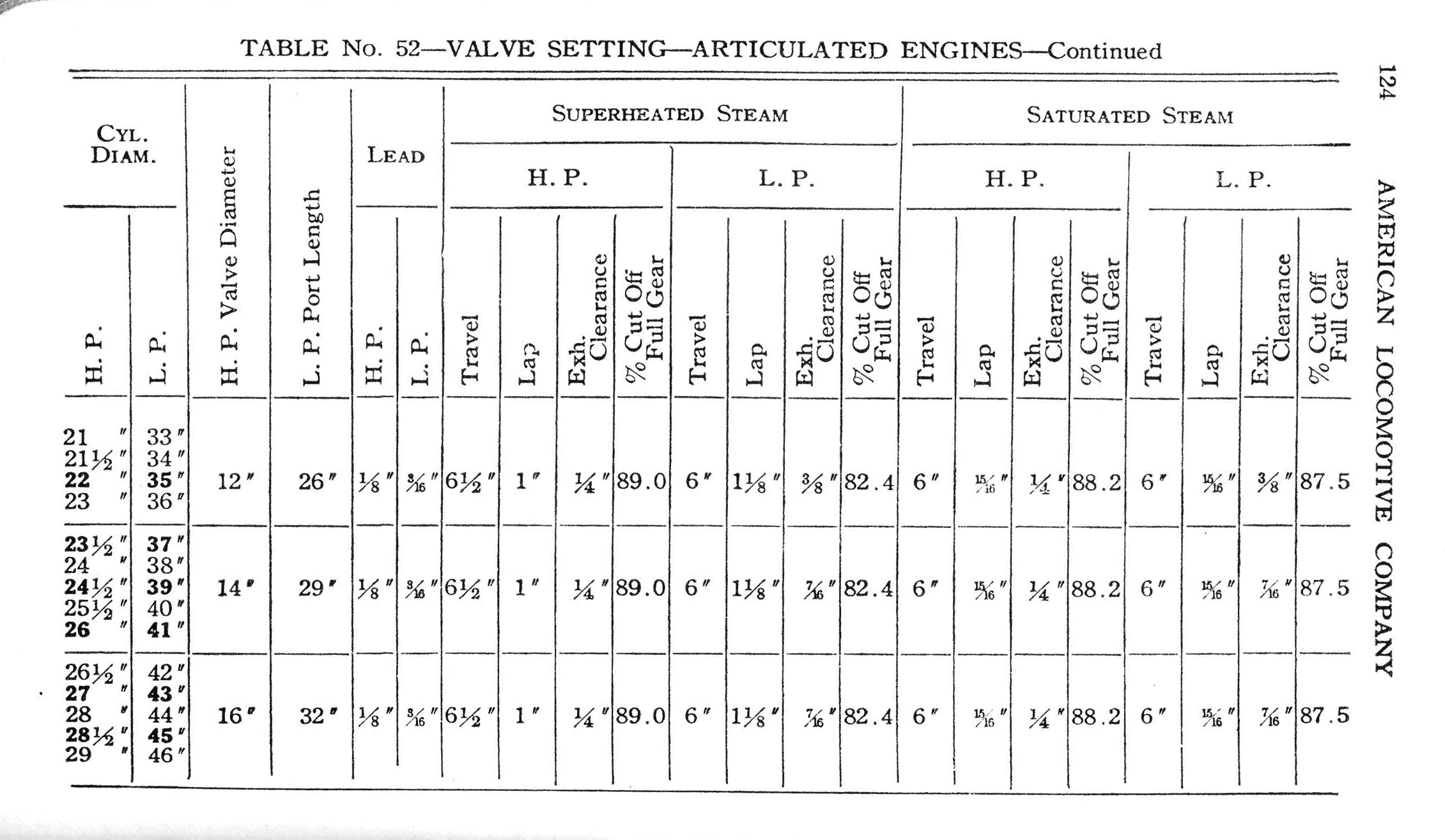
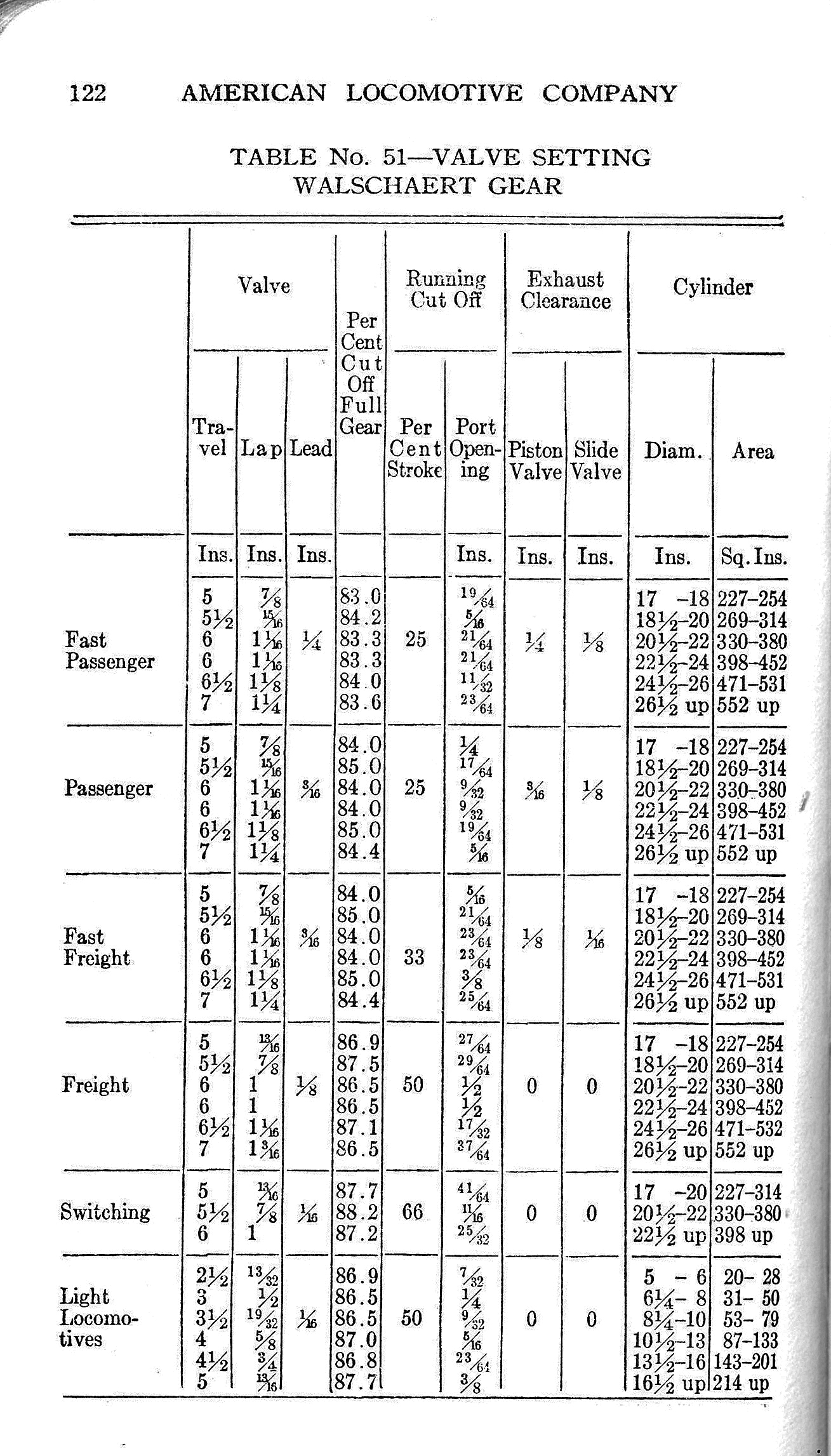
While there are probably design specific equations for valve gear, my guess is they are derived from the principles for simpler four bar linkages. I doubt that machine shops building steam locomotives ever just whipped out a valve gear design, fitted it to a locomotive, and just ran it to see if it worked… instead this is the real domain of an engineer with pencil, paper, and the patience to sit down and calculate the math! I figure once enough steam engines had been designed, built and standardized, the results of common equations were written out into the tables that have been shared previously to the thread; allowing engineers to speed along design without having to re-calculate the valve gear layout every time they drafted a new engine.
To solve a system in the modern era really isn’t much different. Once an equation is written to govern the behavior of the valve gear a computer program in Python or Matlab could be written to test the effects of different driver sizes, piston bore sizes, and linkage size lengths, generating a table of design options. I’m pretty sure if I asked around enough I could dig up and run those equations through a computer program pretty easily with just a bit of coding. The modern era has the blessing of CAD, meaning the valve gear could be drawn up in SolidWorks, then digitally assembled and animated to test its performance in a simulated system.
If I’m understanding the Walschaerts valve gear correctly, the animation has some inconsistencies.
Both the piston and valve should only have rods toward the rear of the engine (Thanks Ed and selector). There should be no rods toward the front, nor a space for them.
I believe live steams passes through the middle of the valve, between the heads. Since it appears that the valves are open for this flow, I believe the animation incorrectly determines the valve position.
With the Eccentric Crank set 90 degree behind the side rod bearing, I believe the Radius Link should be on the lower half of the Expansion Link for forward motion.
There appears to be an additional link connecting the Radius, Combination Bars and Valve Stem to the frame. The Radius Bar should connect to the Combination Bar at the top, the Valve Stem to the Combination Bar just below the Radius Bar and the Union link at the bottom of the Combination Bar.
The direction is correct - this animation is of an outside admission valve, not that the live steam is at the very front and very back of the valve. In other animations, the example is an inside admission valve where the live steam comes in at the middle of the valve, therefor the the valve needs to move forward to allow steam into the front of the piston to push it back. In the animation here, it’s just the opposite - the valve moves backwards to allow steam in to the front of the piston.
The extended piston and valve rods were common for a certain period, if you look at pictures of steam locos, mostly all prior to the turn of the 20th century, you will see the supports sticking out the front. Outside of additional guidance for the valve and particularly the piston, perhaps reducing wear of the piston against the cylinder bore, I don’t know what other pupose this would have served, but it definitely existed. I suspect later advances both in the materials used as well as beefier crossheads, eliminated the need for additional support at the front of the piston.
There is one mistake in the drawing, for outside admission Walschaert’s, the radius bar should connect to the combination level below the axis of the valve stem.
Here is ‘the original’ animation of Walschaerts valve gear, which is a depiction of outside admission and which also depicts the combination lever being ‘met’ below the pin connecting the top of the lever to the radius arm.