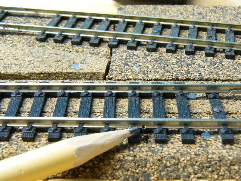
Tha appearance of laying a 22 awg feeder alongside a ppiece of code 83 rail and soldering it in place is unsightly to me.
Is there a better way?
Tha appearance of laying a 22 awg feeder alongside a ppiece of code 83 rail and soldering it in place is unsightly to me.
Is there a better way?
You could try soldering to the bottom of the rail before laying the track. Or… you could file most of the feeder away like I do, leaving very little visible even before the track is painted or ballasted, which all but disappears after.
Guaranteed this will result in a bunch of “oh totally unreliable, it will never hold up” replies, but I have NEVER had a problem with this, and that includes after applying multiple coats fo paint to said rail joiners, but my method is to simply make the rail joiners the feeder conenction. I make up and have on hand a few dozen sets of joienrs with the feeder wires attached, so I don;t have to stop in the middle of working to make more. Every single rail joiner (except insulated ones, of course) is a feeder. Yes, that means 6 wires at every turnout (7, counting the frog power wire which I have yet to connect). . No blinking headlights, no sound dropouts, no stalling. And I’ve NEVER cleaned my track, either, other than to remove stray paint from the painting process. The areas I haven’t gotten to with the paint yet are exactly as they are when I pulled the sectiosn of track from the box and put them in place, it’s been a few weeks since I ran a train but I could go to the train room right now (if I was at home), turn ont he power, and start a train and have no problems.
Since the feed wires are on the bottoms of the rail joiners, they are essentially invisible. I also never reuse joienrs. I take a fresh pack, sodler feeders to them, and then sue them when laying track. Pretty much the first and only time one gets slid on a rail is when placing the track. In a tight area where a bunch of cutting and fitting might be required, I have a few strays that are quite loose from multiple use, I use those until the track is cut and filed to fit, then I install the terminal joiners and lay the track in place. Other track brands may have different results, but I use Atlas track and joiners and they fit very tightly on the Code 83 rail. These are what Atlas calls ‘universal’ joiners and are supposed to work with Code 100 rail as well - I can’t imagine.
–Randy
Bruce, I don’t know if this is better, but it’s the way I’ve done all my feeders. Note: my rail is all code100. DJ.
I feel your pain. Some of my early attempts of 22 ga. to C55 N scale rail look pretty horrible. On my next layout, I plan on soldering to the bottom of the rail. I did that on my roundhouse tracks and you can’t even see the wires. I think Andy Sperandeo made his wires look like spikes. He would put some solder on the tip of the wire, bend it over 90 degrees, and flatten it out. If the flattened out part was too large, he would snip off some on the sides until it was smaller and resembled a spike. He would feed these wires up through a hole he drilled on the outside of a tie, and solder it to the outside web of the rail. It looked barely visible, and after painting it almost disappeared. I believe he describes his method in one of the wiring books he authored.
Scott
Bruce,
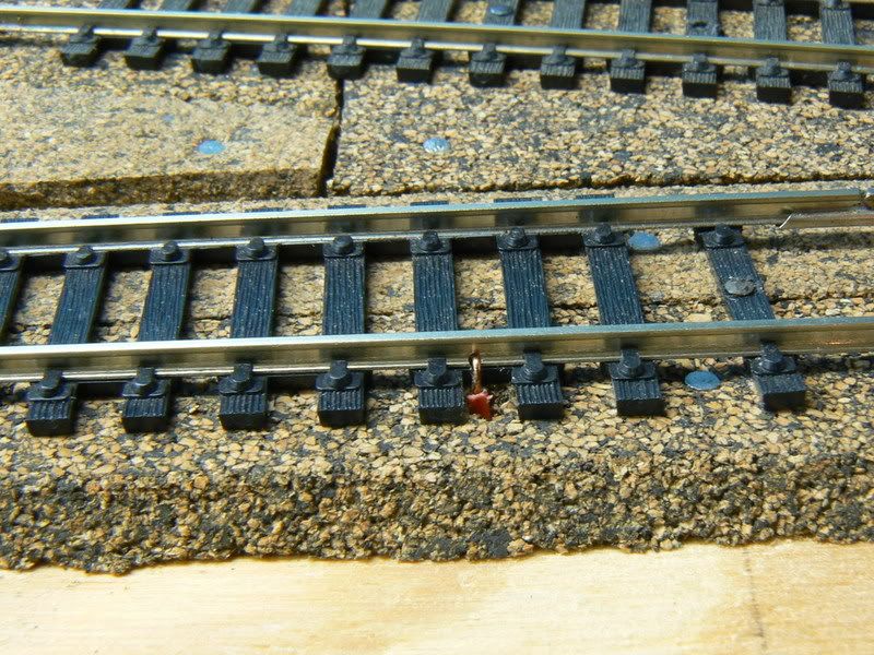
I solder to the bottom of the track before installing. Easy to hide and solves other problems as well. I use bare copper 22 0r 24 wire soldered to the bottom of the track and then install the track. I drill holes next to the track and feed the wire through. The wire gets buried in the ballast.
A view of the feeders un-ballasted:
Guy
I use a technique similar to Grampy’s except that I use a pair of needlenose pliers to first flatten the end of the feeder wire then bend it 90 degrees. I then use a pair of miniature diagonal cutters (dikes) to trim the flattend wire end into a rail spike head shape. I then apply paste flux and tin the shaped wire end with solder. I also apply paste flux to the rail web where I want to attached the feeder wire and tin the rail web. Be careful not to melt the ties. I drill a small hole between the track ties to feed the wire down through the layout deck. After adding a little more paste flux to the feeder wire end, I insert the wire into the hole in the layout deck and align the feeder wire spike head against the rail web in a manner similar to the way it would be done on the prototype (though not through a tie). I often use the blade of a hobby knife to hold the feeder wire in place while I solder the wire/rail joint (the solder won’t stick to the stainless steel blade). The tinning process and the final dab of flux means that very little heat is needed to join the feeder wire to the rail. Heat the joint only long enough to get the solder to flow freely between the rail and feeder wire but no longer. Don’t move the wire (or hobby knife) for several seconds after the soldering iron is removed to ensure a strong and electrically “hot” joint. The finished joint should be a shiny silver color (almost like chrome). A rather simple joint strength test is to grab the free end of the feeder wire under the layout deck and pull down firmly (don’t pull so hard that you bend the track). If the joint survives the pull test, it should remain a good joint for a long, long time. Oh yes, I find that a small 35-40 watt pencil tip soldering iron works great for this method.
I attach feeder wires to the rail joiners before hand and haven’t had a problem. I solder many joiners to the rail as well. Never had a problem and don’t have a feeder every 3 feet. Averages about 10 to 15 feet, maybe a lot less depending on turnouts which need around them many times.
I use stranded wire(I know a lot don’t like it) because it solders so easily and easy to deal with. Never had problem poking it down through the layout for many inches. The key there is to not strip the free end until you’re ready to attach it.
Richard
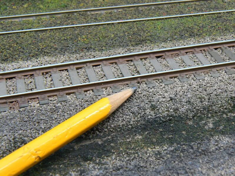
Those feeders can be unsighly, sure, but they don’t must be. If you keep the ends tight against the foot of the rail, and then against the side opposite the common viewpoint, they won’t be seen once they are soldered into place and painted.
I do the two-angle elbow bend, keep it tight to the rail, and try to solder it as low toward the foot as possible to avoid flange hopping. I do the close rail with the feeder on the opposite side of the web from view, but also the far rail that way. The result is that one rail’s feeder is between the rails and the other is on the outside.
Crandell
Most model scenes are only viewed from one side. Prop a mirror where it needs to be so you can observe the workplace, then solder the wire to the side of the rail you can’t see when operating normally.
I bury feeders for my hand-laid specialwork in the flangeways of frogs and guardrails. Hides the feeder while reeinforcing the joint.
If you keep the funny-colored insulation below the bottoms of the ties and dab the exposed wire feeder with a black or ballast-colored Sharpie, it will effectively disappear.
Chuck (Modleing Central Japan in September, 1964)
 And what is wrong with wires attached to your tracks?
Does anyone know the ga of the wire on the Atlas rail joiner feeders? Is this ga wire ok for a 3.5 amp DCC system, feeders every 3ft, 82ft mainline? Thanks
Like Randy, I solder feeder wires to the bottom of rail joiners.
That is not necessarily a foolproof method, however.
I have had several instances over the years where the ballasting glue mix gets between the rail joiner and the rail, effectively cutting off the power supply to the rail.
Rich
I know a lot of modelers don’t like to do it, but I solder all rail joiners. This is basically why. I have the advantage of having my layout in a climate controlled basement, er, train room.
Good point, Marlon.
Medina1128,
I’m with you. I solder every rail joiner, including turnouts. (Having built two garage layouts in the high desert with its temperature extremes, I never had issues with expansion). I also solder feeders to every section of rail on the layout, including the stock rails and the frog on turnouts. Like Randy, my locomotives all can crawl smoothly across the multiple switches without hesitation or flickering lights.
I file out a small notch in the rail web to make sure the wire fits snugly against the rail. If I think the solder blob looks too large, which is rarely, I file it down. Once painted, it’s invisible unless you really want to hunt for it.
John Timm
I’m with you too Marlon. I solder nearly all rail joints, especially around turnouts. I have no electrical continuity issues, and virtually no derailments (the few that do happen are almost all operator error). I can paint, weather and ballast with no concerns about electrical problems arising due to paint or glue interrupting elctrical flow, plus the track never moves out of alignment.
So, how do you guys do it?
Do you solder feeders to the rail joiners, lay track with the soldered rail joiners in place, test the track, then solder the rail joints onto the rails?
Rich
I may have missed something in reading but I don’t remember anyone advocating the use of PC board ties; these are – or were – available from Clover House.
I have to admit, however, that I have never used this procedure; there have been, however, a number of articles in the hobby press advocating their use that I do not question the workability.
I have been a user of Rail Craft/Micro Engineering N-Scale Code 55 rail/flextrack for over 25 years. Over the years I have used the traditional:
. . . . .1) solder-to-the-rail-web;
. . . . .2) solder-to-rail-joiners;and
. . . . .3) solder-to-the-underside-of-the-rail
techniques. Of the three I prefer the latter and it is the one I usually use.
On my latest layout I used a technique I found in an old 1950’s era MR. At a tie location I drill a #74 hole through the web of the rail as well as through the tie on the inside of the rail. Using #28 gauge solid wire – you could use #32 gauge wire and a #76 hole but I could never locate #32 gauge solid wire although I was assured it did exist – I strip an inch or so of insulation from the w
I like this idea of drilling into the rail web, as I also use code 100. I converted to DCC from cab control a couple of years ago, and just wired the DCC system in place of the primary throttle. I just rewired what become the first power district, removing the cab control feeders to the control, connecting them to a 12 gauge bus and adding a couple dozen new feeders. This idea of of drilling into the rail web will be handy when I rewire the next power district. My new feeders are the old blob of solder on the rail web technique.
New track that I have laid in the past couple of years has been with the wire-on-the-rail-joiner technique.
George V.