Has anyone ever tried creating their own street lights or lamp posts from scratch? I’m trying to build a small downtown layout and find the cost will build up quick if I buy them.
Just wondering if there’s any previous attempts at making them worth sharing.
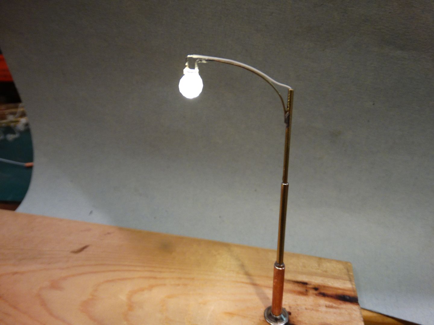
I have made 1950s era street lamps for about $3.00 each:
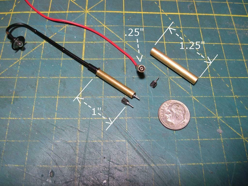
I used a 3mm LED and brass tubing and strips. The base is a washer used for counter sunk screw heads.
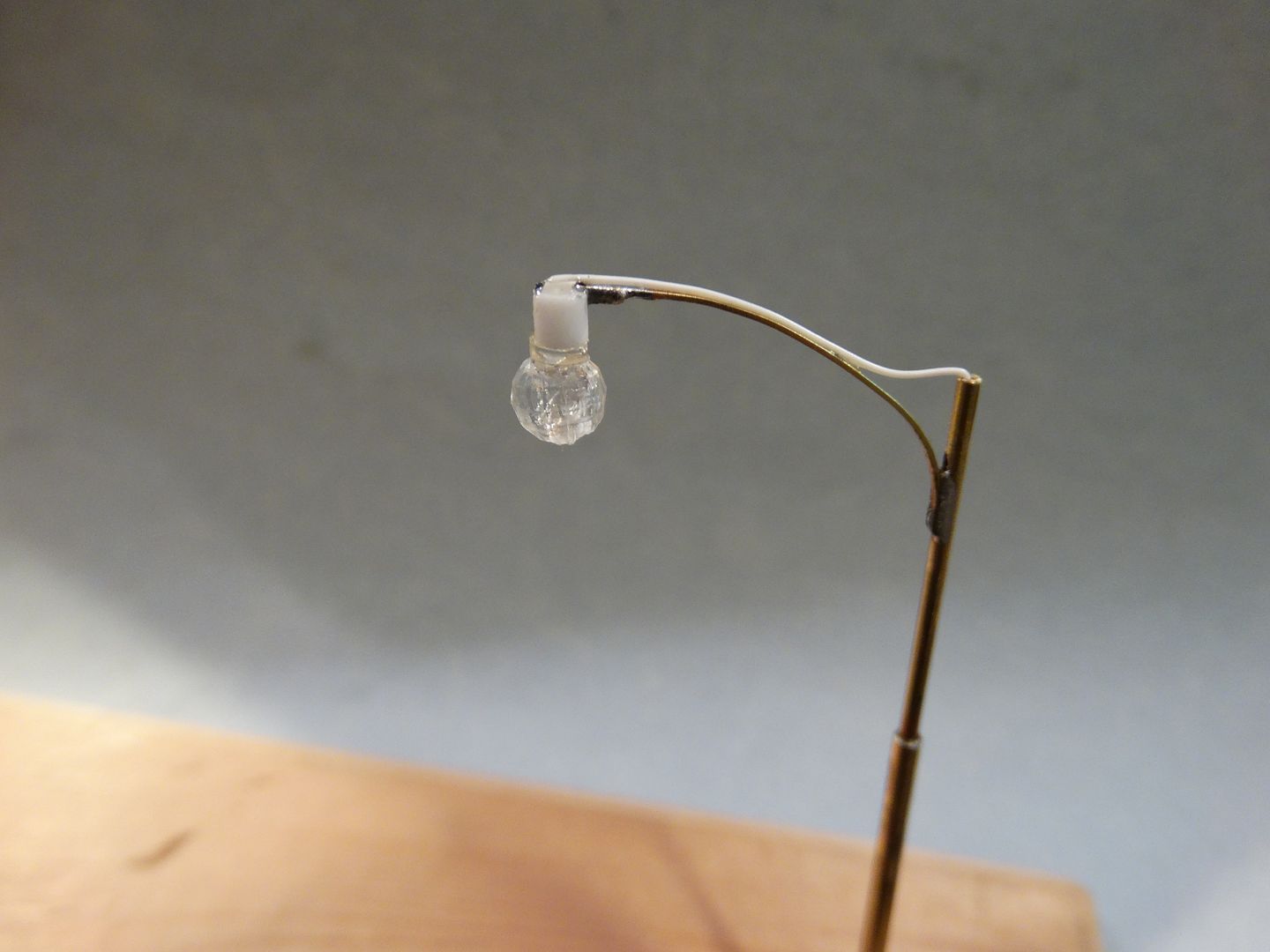
Here is a view of the basic pole. The globe is an 8mm plastic bead. They are plentiful on eBay. If I was doing them again I would use a 5mm bead and an 0603 SMD LED:
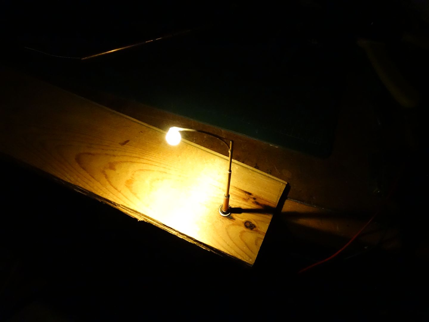
The brass pole serves as one conductor. I am still working on a socket system which will allow the lights to be removed from the layout by simply unplugging them. I’m experimenting with low voltage power sockets. This is my first attempt. See Mel’s post below for a better socket system.
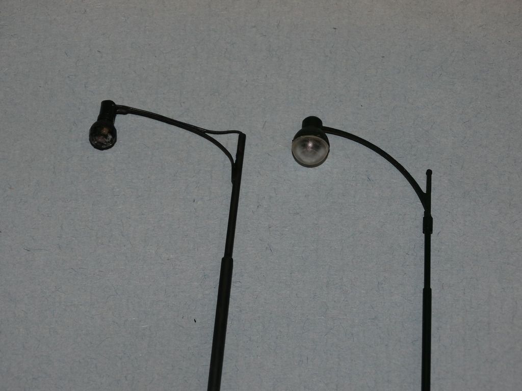
They look reasonably good when painted. My lamp is on the left. The lamp on the right is a Walthers Built Up model which cost somewhere in the $18.00 range each!
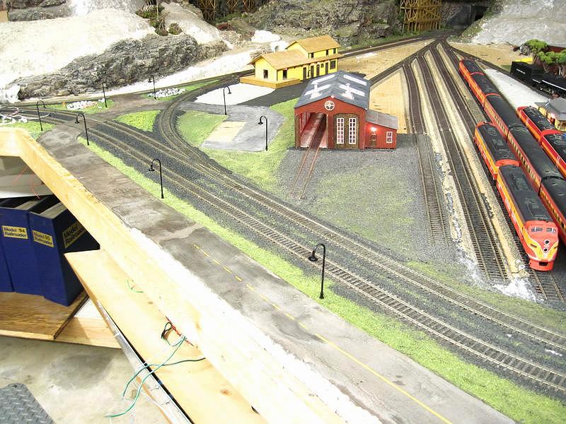
I have made lots of Tom’s yard lights too, based on his inspiration. They are quick, cheap and easy, and they look great!
Ok, I’m glad to see there are examples of scratch built lights and these look much nicer than store bought. Originally I was looking at just Walthers catalog and found it a bit expensive to install 30-40 lights but thanks to RR Mel, realized you can find them on eBay or Amazon for much cheaper.
But, I still like these home made options better. Thanks for sharing everyone.
Is the voltage different for these scratch built lights?
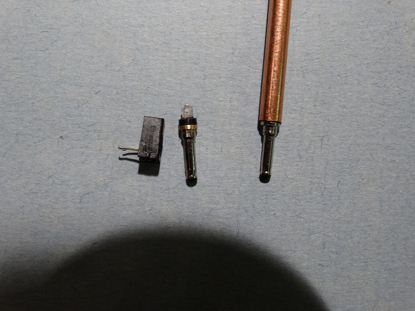
I soldered a single male connector to the lamp wire and glued (CA) it in the bottom of the support tube. I used short brass tubes to make a base/socket using a female connector to mate up with the male.
Actually I use 12 volts and a suitable resistor, somewhere around 2200 - 3300 ohms. Using a 3 volt power supply would be easier but I think you might still want to experiment with small value resistors to get the desired light level. I don’t like the street lights at full brightness. I prefer a bit of a yellowish tone.
One advantage to using a 12 volt power supply for accessories is that everything can be powered from the same source(s) so there is no confusion about which is the 3 volt wire and which is the 9 volt wire etc. etc… All the accessory bus wires are 12 volts. Just don’t forget the resistors!
By the way, Mel’s sockets are easier to make and much stronger than mine.
Did you give my connector a try, they have worked out pretty good for me. I did the connector thing about 7 years ago and I have removed and reinstalled them many times without a single problem. I got the idea from a Walthers Bishop’s Crook Street Light.
All of my structure and street lights are incandescent 12 volt operating at 8½ to 9 volts for realism and extended bulb life. I went with switching power supplies for better efficiency, better efficiency means less current draw and less heat dissipation. Regulators and resistors are inefficient and draw unnecessary current and dissipate heat.
My accessory power is 12 VDC and I use switching DC to DC converters to set the operating voltage needed, again much less heat dissipation that regulators. The regulated switching DC to DC converters are cheap off eBay, under $4 for 8 amps. They can be adjusted from 1 to 24 volts and are very stable. I have one set to 1.4 volts for my hundreds of 1mm 1½ volt 15ma micro bulbs used for headlight and taillights in my vehicles. The converter h
I had forgotten about your sockets until I saw your post. I will use your design when it comes time to mount the lights. The components that I used are too small and fiddely, and I suspect they wouldn’t stand up to repeated removal, and yours are much easier to mount. The female socket on mine will be a PITA to get lined up properly.
You are making me re-think my overall power strategy too.
I wish I had seen your vehicle connection methods before I wired my vehicles. I’ve got a whole bunch of cars and trucks with all sorts of wires dangling out the bottom that will be a pain to install.
I don’t know where the idea came from to use brass rod and tubing to make the vehicle connectors. They do work great for my layout. The real benefit is the ability to move my vehicles easily around my layout. I have about 95 vehicles with lights and I installed about 120 sockets around my layout. There is a down side, if you don’t make an accurate drawing of socket placement they can be very hard to find.
I use three prongs on vehicles that have flashing emergency lights. I’m not happy with the three prong connectors but I haven’t come up with anything better. I only have a couple of extra three prong connectors for vehicles with flashing lights so placement is limited.
I made a separate flasher (total of 9 vehicle, 5 fixed beacons) for each circuit so that they never flash in sync. I went with a simple two transistor flip flop circuit for each flasher, all the componets are the same for all flashers. even when they are first turned on there is no flach sync.
I fought the power problems on my layout for years, I never liked using regulators because of heat dissipation problems. The answer is DC to DC convertors. They are current and voltage adjustable with almost no heat dissipation.
Before I switched over to the convertors I was using regulators and they needed fan cooling, the 8 volt regulator was running 7 amps (over 80 watts of heat dissipation). I have pulled all but one fan because no heat problems using the convertors. My control panel has two transformers, several wall warts and three DC to DC convertors. One 3” fan keeps my entire control panel cool.
Mel
Modeling the early to mid 1950s SP in HO scale since 1951
I just ordered some DC to DC converters. I ordered three like yours, and I ordered three that have a digital readout built in that will show either volts or amps both in and out. The ones like yours are good for up to 12 amps output. The ones with the readouts are rated for 2 amps out.
I will also go back and have a look at my vehicles to see if I can simplify the wiring. If I can use the DC to DC converters I can eliminate the resistors which would hopefully allow me to adopt your post and socket system for most of my vehicles.
Learn something new every day! Thanks for the ideas.
Well that’s a bad question for me. I did the basic wiring 30 years ago and through the years I stayed with my original concept. I don’t use buss wiring for my layout but I do use buss wiring in my control panel. Since the control panel wiring is short runs I use #16 for up to 10 amps and #14 for high current. My longest bus is less than 4’.
I also use #20 bell wire for my block wiring using home runs to a Euro connector in my control panel.
I have home runs from every accessory to my control panel. A couple of years ago I found some #26 ribbon cable that I use for structures with a lot of lighting (Arduino Random Lighting Controllers), sure beats using Telco wire. My turnouts use #20 three conductor bell wire (red/green/white) from Home Depot.
All of my vehicle wiring is #24 Telco wire home runs, a blue/white pair for non emergenc
No, not at all! Your methods work well and therefore deserve due consideration. My layout will be a bit bigger than yours (12’ x 23’) but the distances from the accessories to the five individual control panels won’t be much different so ‘home wiring’ is definitely an option. In fact I can see it being easier to trouble shoot than using buses.
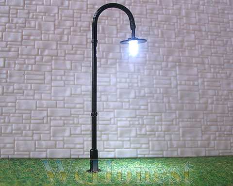
I also purchased (30) HO scale street lamp posts from the same Ebay seller. This Ebay seller (wehonest_cn) is selling (20) HO scale street lamp posts for $23.99 (US $1.20) each.
All the hardware is made from brass. The LED used is a 5.MM (.197" Dia.) white LED (blue tint).
HO scale street lamp posts:
I personally do not like the large size or the soft blue color tint from this LED. Especially when I am building a late 50’s, early 60’s era model train layout.
I will be replacing these LED’s with much smaller 3.MM (.118" Dia.) (Warm White) (Diffused Round Top) LED’s.
You RR_Mel informed us that you were an electrical engineer 30 years ago (1987). The pictures you supplied from your main power control panel, looks very clean and very professional looking. You stated that you use #20 wire (0.032" Dia.) to a Euro connector in your control panel.
On my very first attempt to wire my (27) Circuitron Tortoise Switch Machine’s, I have #20 wire (0.032" Dia.) (to 54 Euro terminal wire connections). After doing wiring testing, (1/3) of the wire connections failed to have an electrical connection. Latter I found out that this type o
I use the 3 amp Euro connectors they easily handle smaller wires without any problems. In fact I also use #24 & #26 TELCO Frame wire in the Euro connectors and I’ve never had a problem the smaller size wire either.
I worked in two-way radio communications for 49 years and 10 months so I do have a bit of experience in electronics. I retired December 28th 2007. I got my degree in 1960 from Texas Western College now University of Texas El Paso. I began my electronics career in February 1958 working for a Motorola Two-Way Radio Service Center in El Paso.
I also use the US version of the PCB screw terminals on my Arduinos. I’ve never had any problems with my wiring. I’m a gadget guy and to me model railroading is a blast from the past.
Mel
Modeling the early to mid 1950s SP in HO scale since 1951