I’m still in the middle of building my new double decker HO. I’m thinking ahead as I will need about 6 control panels that will give me indication of switch status and other things such as track occupied, etc, etc, when we’re eventually running trains. I have DCC (NCE) and I’ll be switching using DCC. So … any ideas guys about how to make good graphically designed control panels that give all the visual indications. Especially lessons learnt!
I use birch plywood for my panels. I picked out a nice “panel green” color for the background. I used striping tape from the LHS for the track diagrams, and vinyl stick-on letters from Staples for the lettering.
I used LEDs for all the switch position indicators (green for normal, yellow for reverse). I don’t have any occupancy detection, but LEDs are great for those indicators as well.
If you’re using the DCC throttle to throw the turnouts, it would be a good idea to put the turnouts’ DCC addresses on the panel as well.
I bought a 4x8 sheet of bathroom shower liner material. It’s about a quarter-inch thick and it’s a pressed paper product like masonite, but with one side covered with a thin waterproof plastic veneer. It comes in colors, but I chose white. It makes good control panels because it’s easy to work with, very cheap and you can stick on labels or lines. I used automobile pin-stripe tape for the lines.
I also use bi-color LEDs (red/green, in my case) to indicate turnout position, and simple miniature SPDT toggles to throw the turnouts.
For my lighting control panel, which is not schematic, I printed up labels on the computer and taped them on.
I had same need and pursued many suggestions on this forum. About a couple months ago in Model Railroader there was an article on making control panels using the clear plastic (about 1/16-1/8 thick) sheets you get at Home Depot or whatever. Sorry, but I’m not where I can look up the article for you.
I made two panels using instructions exactly as in the article. They turned out wonderful. Cheap and easy. You create the yard layout diagram on the computer (I used Wordperfect but other text or drawing software works). You print the diagram (I have ink jet printer) out on regular paper. You snap off the clear plastic to make two pieces the same size as the diagram (mine was about 8" x 10"). You put the diagram between the two sheets, temporarily tape it on the sides, and this will be the panel. You then carefully drill a small hole every where you want a switch or LED, (through the top sheet, the diagram, and the back sheet). Also holes in each corner for mounting the panel. You then gradually use a larger, and then larger drill size until the holes are the proper size for mounting the switches and LEDs. In this way, the plastic will not crack or have spider type cracks around the holes.
You mount the switches and LEDs (I used LED holders from radio shack), turn over the panel and bring the wires in and solder the connections to the switches,LEDs, resistors, etc. I used small self adhesive plastic cable wire holders, to keep the wires coming in and out neat. I also wrote and identified the wires and connections on gummy labels and put those on the back of the panel, in case I ever forgot where the wires come from or go to.
You then remove the temporary tape, and mount the panel at the four corner…I used a fancy washer with the screws. It is easy and looks great. Some tips that worked good for me. I
I built mine with two sheets of plastic and a piece of thicker paper, nearly cardstock. My color inkjet printer could handle paper of that weight,a nd unlike normal printer paper it didn’t tear when drilling holes. I drew straight and diagonal lines using Visio, color coded for maina dn siding, and also put proper diameter black dots where holes needed to be drilled for the toggle switches and LEDs. The only thing holding the three pieces together are the nuts on the toggle switches, and the screws holding the panel to the layout. I think thee’s a picture or two on my web site. This probably isn’t my final panel design so I never made a nice frame for them or anything.
Make the fascia the panel, put the controls right next to the switch they operate. Very few if any of my friends have control panels even though our layouts run one or two visible levels and anywhere from 250-2500 sq ft. About the only place they have a control panel is to control hidden staging from an aisle.
Why spend all the money to get a 21st century DCC system and then build 1945 style control panels?
I totally agree with the thought about building a 21st century control panel. That’s exactly my view. The panels should be smart, clean with LED’s giving simple informaion at a glance. This is my retirement layout and I must be able to READ them!!! (The worst enemy of this hobby… deteriorating eyesight!)
I like the idea of clear plastic sandwich with a graphics printout in between. I have Dreamweaver which is used for web design and I’ve already designed the logo for the layout.
As I’m building a three level climb up and around my layout to get to and from the lower layout to the upper, I’m thinking of naming each level as a town and having IRDOTs that wiill trigger LED’s on one panel so that the climb stages can be seen. As the climb track is single, it will also give me a view of occupancy.
The other thing is to note the DCC address of each of the switches on the panel. Together with LED’s, the action thru the handset will be confirmed on the panel.
Any problems with scratches on the clear plastic anyone?
Here’s my control panel - two plastic sheets with the graphics sandwiched in between:
I made the graphics on the computer. I’m in the process of adding IRDOTs to my staging yards and occupancy indicators (green/red bi-color LEDs)on the panel, plus blue LED indicators to show for which yard track the turnouts are aligned.
Here’s an early view of the guts of the panel when I was first building it:
first for the design i am a acad user so i make the panel graphics from acad.i print it out on regular paper i use the centers of switch holes to mark the holes on the woodpanel. then i get my laminator out and laminate the graphics. then i get out my hole punches and punch out the right size for whatever hole size i need. i drill the wood panel for the holes needed.as you can see i color code tracks and give car capacities for each track based on hopper sized cars since thats what i have most of. i also make these for local switches along the layout
here is the back of a different panel. i use a magnet to keep the panel door shut
this picture shows the panel cabinet the graphics on this one was a early version without the laminate yet.
correct no sandwich of plastic. the lamination is on both sides of the paper. i let the switches and hinge bolts hold it on to the wood panel. no problems yet with it lifting off. i could always glue them on if it does. the switch is a master power for the panel to turn off or on all the switches.
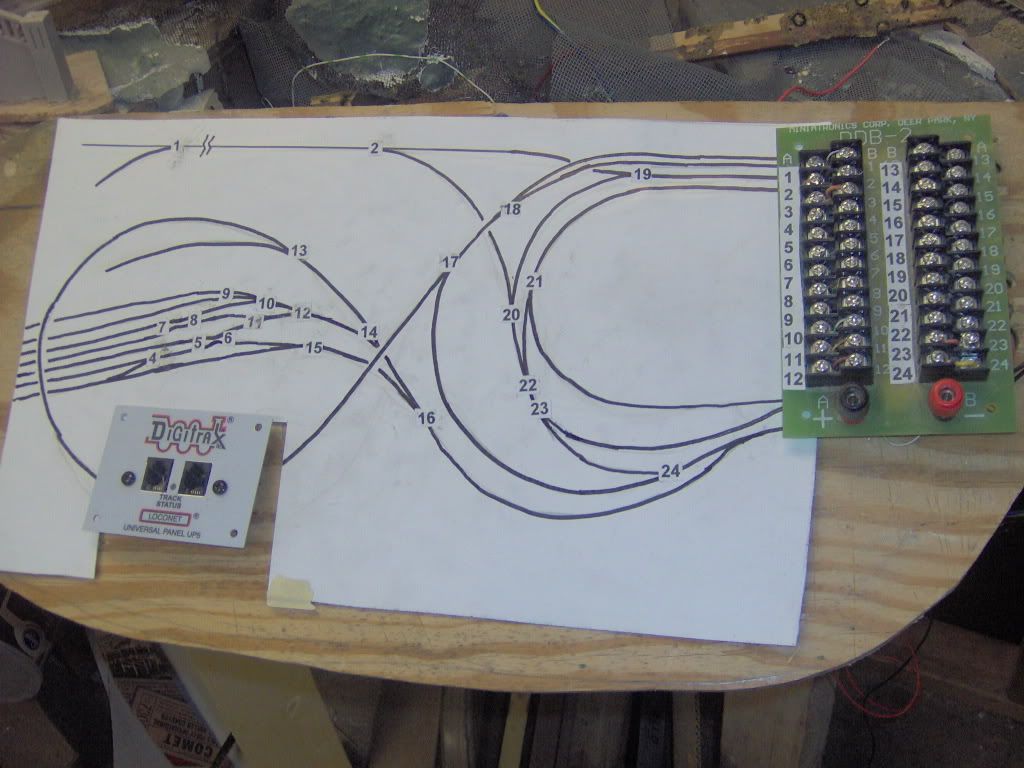
My 24’x24’ layout contains 240yds of track and 102 switches, was originally DC. I have since changed to DCC Digitrax SuperChief (since I needed 8amps to operate) While this may be the 21st century, I could not afford to replace all the switch motors with DCC contols. With all the curves and reverse loops, I decided to distibute the controls to four power districts, with four tethered control panels. The operator at each panel has a good view of their 24+ switches, to control with a grounded probe (to touch numbered double 24pin contacts, corresponding to the numbers of the switches shown on the enlarged drawing). I used an enlarged drawing, rather than the usual schematic graphs, since it is less confusing to refer to the drawing of the actual layout numbered switches, rather than have to translate the schematic drawing. The controls are presently mounted on painted plywood horizontal panels, which are hinged for drop down track access. Eventually, I will follow Brunton’s ideas of mounting IRDOTs, plus occupancy indicators and blue LED indicators
Perhaps my thinking is colored by my work as a helo pilot and in designing command posts where the operators have to manipulate multiple systems - some integrated, some not.
I tend to agree with Dave. I prefer to concentrate on running my train - taking on the roles of engineer, conductor, brakeman. I have no interest in being the traffic cop (dispatcher). The dispatcher is the only one who needs a light show and Star Trek display.
The dispatcher position can be done away with if you require each train to clear their own track ahead of them - akin to VFR flight rules where a pilot is responsible for clearing his uncontrolled air space. In this situation, move the needed occupancy lights into functional signals along the track instead of lights on a control panel. The signals are only needed where the engineer can’t see to visually clear his way. Same for turnouts and remote uncouplers (if used) - local controls on the fascia where the train crew can see which way the turnout is thrown or that the cars are spotted properly for uncoupling. Again, use signals for turnouts that can’t be seen. Local direct control with needed signals actually on the layout leads to eyeballs on the layout, not a light show at a control panel.
Note the above doesn’t work as well for night operations (neither does VFR in the aviation world).
There are other valid operational styles and preferences - I have described mine. Mine does have t
Yes, I agree partly. I must admit that I always watch the train and I only had one control panel on my previous layout with no LED’s at all. This time, I think it’s good to have LED’s to confirm routes. Also, I really do want to have control of my layout lights that will allow night to day to night. (Don’t ask how I’m going to do this yet, still working it out.) So LED’s would be great for easy reference on the panels. I also want to have the option of running the whole thing on my own, so I think such panels would help there.
As for a panel for each working section of track, that’s exactly what I’ll be doing. The panel will be the info centre for each section under the control of an operator. Learning from my previous layout, I want each panel to be simple, easy to see and read and to give easy information of routes and switch positions. I’m also very much up for flipping switches and routes using DCC. I thing it’s technology there to be used.
On my own layout, control panels are used only for hidden staging. Train occupancy and turnout position indicators are used only where the turnout and the track can’t be seen. Visible turnouts are hand thrown where reachable. Others will be thrown by Tortoise machines controlled by a facia-mounted switch.
So THAT’S what it is! [:O] I bought a sheet of it at HD a while back but there was nothing on the shelf to identify it. But, I liked it and it was really easy to work with so I used it. Now I know!
I use automobile pin-stripe tape too, but a bit differently than you did as I suspect you used the tape itself for the lines. I put the tape on the panel then put a couple of heavy coats of latex house paint over the whole thing. When the paint was dry, I removed the tape. I then painted the lines different colours with acrylic model paints, a different colour for each block. The heavy coats of house paint left minute ridges at the edges of where the tape was, so the paint in the lines stayed in the lines. Also, like you, I’m using toggle switches and bi-colour LEDs. Nice to see someone else with the same ideas as myself.


 |
|