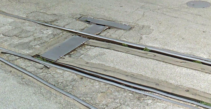
Doing a bit of street railroading on my layout. My planned setup is to have a freight line run down the middle of a 2-lane street. I also want to put a switch on this line (and, thus, in the middle of the street). The setup will thus be similar to what’s happening in this photo. I am going to build my road using plaster of Paris (or a similar product) and mold it carefully around the switch, such that the points can still move. However, I don’t know how I’ll be able to control the points after the road is finished. Would a real railroad put a ground throw in the middle of the street? Or would the throw be located off the street and be connected to the switch via undeground moving parts?
If it helps, I’m in N Scale and the switch will be a Peco small radius insulfrog switch.
It varied, but when a switch was in the middle of the street, there was often a square steel box embedded in the roadway which held the throw mechanism.
Looks like one of the gnarlier parts of Houston. Great pics, Bear! Also good because they illustrate something about those boxes that hold the throw. Often, they are between the rail as in these pics, although they can also be in the more typical to-the-side location.
MR has had some great articles on street-running over the years,w hich is where I picked up most of what little I know, plus seeing street track various places. Thing is, you really can’t see much of anything, which is where the MR articles are good at illustrating. The ones I’ve seen are from the 70s on, although I’m sure probably older ones. Check the Magazine Index elsewhere here on the MR site for refernces to them.
As for modeling the throw, you don’t really. Just use whatever flavor of undertable switch machine. Manual throws can work, too. I’d just make a dummy cover and glue it to the road, but I’m sure someone has figured out ways to do it from on top. Peco turnouts with the over-center spring could probably work, as you could flick them whichever wayI think.
One technique I’ve seen puts a standard switch stand just behind the curb line (adjacent to a fire plug, IIRC) and the linkage under a hinged steel cover across the parking and traffic lanes to the points.
Why next to a fire plug? To take advantage of the red curb NO PARKING zone to assist in visibility.
Another possibility is to use a single-point streetcar turnout built of girder rail. Since street running rail traffic is (very) speed restricted, this is a practical option. The single point was usually thrown with something like a crow bar. It had an over-center arrangement similar to a Peco switch to hold the point in the selected position.
I’m in HO and have two Atlas #4’s in a brick street, plastic. The ideal set-up would have been undertable machines, but could not do that because they are directly over the bench bracing. So I dug a six inch long trench into my sub-road bed, which is Homasote, buried a brass tube with a solid brass rod inside connected to the throwbar the other end connected to a Caboose Ind ground throw, works perfect. I use all N-scale # 206’s by Caboose Ind. ground throws on my Ho-scale layout. Some say that won’t work, but they have been working successfully for me for year’s.
The brickwork for the switches was a pita, measure, cut, file, sand, test, but I finally got it worried and succeeded. Pic’s will be forth coming, God willing.
Modelling using the link as a guide will allow styrene or thin stripwood to cover the throw bar. For manual operation just use a choke cable or set a sw stand off to the side following the previous posting.
Styrene templates (point rail movement) and masking will help w/ applying the plaster {I have better control w/ Hydrocal)
A hint for any dried plaster removal, wet the plaster before shaping/ carving. I also would dye the mix close to the asphalt. Track clraning around such a spot will always cause chipping, showing white spots to have to touch up.
Walthers used to make Street Track Inserts, that also included inserts for switches, 933-3140, they discontinued them, probably due to lack of people buying them, but if you can locate a kit, that would make your job so much easier, just use the brass tube mechanisum, that I described in my other post. I actually used the parts for a #4 switch as a template for my brick streets:
Take Care!
Frank
Edit: Not certain, if they made them for N-scale though.[:(]
See that woman standing on the sidewalk near the Yellow suv? Thats about where my ground throw is, in the brass sleeve.
@richhotrain, that would be the easiest solution to implement, since it wouldn’t involve running a wire through a brass rail to a throw and hoping it all works. Have you (or has anyone else) done that in practice with a Peco (or similar) switch? And has it worked?
Take a look at the pic I posted of the street track inserts, at the switch points you will see a section line in front of the points starting there and going the length of the points until you get a little past them you will see another section line and then tapers to the frog…that whole piece which is one piece, does not move, that is glued to the ties, except for the area at the very beginning of the points, the underside of that area where the throwbar is, has a notch in it so the throwbar will slide back and forth. If you use the spring method, you will have to use a pick or small flat blade screw driver right at the points to throw them. You surely would no be able to use your finger unless the whole area was exposed. To make matters even more harder you want to use plaster, which probably to near impossible and expect it to work. You could use plaster all over the rest of the switch, but the area I mentioned, would work better with a flat piece of plastic over the point area shaped like the one in the pic. It’s a lot easier though in HO, than N.
Good Luck! On what You do.
Frank
The pic below shows the part I am talking about that is one piece, this is from a Atlas snap switch. If you made one of those for the point area and then the rest plaster, it would work, The long part that starts at the point end to the frog:
I don’t have switches in the street pavement in my layout, so you are confronted with a more difficult situation.
I do have some Peco turnouts in yards and sidings that I throw by hand with the finger method. The spring provides enough tension to hold the point rails securely in place.
I raised that issue with the thought that you could design the street pavement in such a way to permit you to throw the switch by hand.