No, you cannot control conventional locos independent of each other, unless there is some kind of electronic upgrade kit that would allow you to do that, however I am not aware that there is.
You can use an automatic block control system that has been used by Lionel operators for over 70 years:

I agree Block systems will work but you will need to lock the engines in the direction you want them running in. And they work better on larger layouts
Kev
Same here, adding a second transformer for cab B would eliminate the need to lock out the E unit’s. You can also use delay off relay’s to make control rail shorter.My friend did it on a 10 x 8 layout. You still need to tweak it to work the you want it to operate, and this can get very complex.I went to TMCC to keep it simple and easy to trouble shoot, and you can run as many trains as space allow’s.
Mike
Not if you use rheostats to maintain E-unit position. With newer electronic reverse units, the bleed voltage can be very low, but you want it to be adjustable to give better visual operation(whether mechanical or electronic).
I run two trains on the same track by putting a rectifier and filter capacitor in each locomotive, so that it is sensitive only to the half-cycles of one polarity. The two transformer outputs go through synchronous rectifiers (each comprising an SCR and a driver transistor) to connect each output to the track only during the half-cycle assigned to it.
This scheme prevents using the usual whistle relay. However, I have my whistles also wired with rectifiers. So, instead of two locomotives, I can control one locomotive’s motor and one whistle tender’s motor, allowing me to “quill” the whistle in a way impossible with a whistle relay. All my whistle-motor rectifiers respond to positive half-wave voltage, since I can always assign the locomotive to the other polarity. Each tender can be switched to normal relay operation if desired.
My locomotive rectifiers use a more complicated switchable bridge scheme than you would need if you limit yourself to a permanent assignment of polarity to your locomotives. I do this so that each locomotive can be assigned to either polarity, as needed, or to full-wave operation, which is handy if running on someone else’s layout.
It is also possible to replace the synchronous rectifiers at the transformer with simple diodes if you are willing to control speed with two rheostats fed from a single transformer output.
1 Like
I find it a lot easier to use TMCC to run multiple locomotives on a single track.
1 Like
I should mention another, much older method that amply predates TMCC. That is to use means other than a center rail to get current to the locomotives.
In the early days of model railroading, it was common to use an outside third rail, like that used on some prototype railroads. Lionel sold outside-third-rail shoes for applying to their locomotives for this purpose. This was done even for steam locomotives, whose pickup shoes were supposed to be unobtrusive.
It is also practical to run models of electric locomotives, like the GG1 and EP5, from overhead wire. In fact, you will find that these locomotives have solder lugs under their pantographs for just that purpose.
By using one of these two techniques along with the usual center rail, you can run two trains independently, or three trains using both techniques together.
1 Like
Well, overhead catenary is a LOT of work to setup and maintain!
I am interested in this topic. I may have 100 conventual locomotives so those who say get command control is a non answer for me.
What I have posted, however inconvenient, are all schemes to provide completely independent control without TMCC (nor DCS nor DCC), as requested. There is another one, Lionel’s “Magic Electrol”, that lets you control direction independently, but not speed: You rewire the whistle relay of one locomotive to operate the E-unit rather than the whistle.
1 Like
For kicks and grins, I made a layout where the two outside rails were isolated from each other for two circuits, and the center rail was ground. I then painted the wheels on opposite sides of two engines with insulating paint. It worked, but the paint wore off pretty fast.
It was quite a while ago, so I don’t really remember how well it worked…but I would guess it didn’t work great or I’d still be using it…
sciencemonter- Welcome to trains.com! [C):-)]
I realize you said “on the same track”, but don’t overlook the simpler solutions.
Since you are considering buying some O-36 track,the simplest way to run 2 engines is to have 2 separate ovals, with the O-27 being the inside loop. Attach one transformer to each loop.
You could add a couple of switches to connect the 2 ovals, using an insulated pin to keep the center rails isolated between inside and outside loop. Maybe add a siding to park one engine temporarily.
Optionally add a CAB-1 controller (12868) and 2 TMCC Powermasters (24130) so you can walk around the layout running the 2 engines. This works with conventional, postwar engines.
If you ever buy a TMCC engine, you need to add a TMCC Command Base (6_12911). You will still be able to operate the conventional engines. Since I have only 1 TMCC engine, about the only advantage is the ability to use the uncouple function anywhere on the layout.
Personally, I rarely run 2 engines at the same time, as I am too worried that one will fall off the track if I am not paying close attention to it.
If you go this way, do not run the train from a track powered by one transformer output to a track powered by another transformer output, especially if the two outputs come from the same transformer. Instead, use a single-pole-double-throw-center-off (SPDT-CO) switch for each track, to assign the two tracks to the same transformer for the interchange. Note that using two transformers in this way also allows you to have as many blocks as you want to buy switches for on each loop and allows you to stop a train in one block while running two others in other blocks.
1 Like
If one is using a rugged postwar transformer, such as the ZW, and not an electronic version, what is the problem with letting the engine cross over the gap between the two sections? I have done this for decades, just approximately matching the voltages prior to crossover.
And why should it matter whether it is 2 transformers or one? These have bimetallic circuit interrupters which would trip if anything was grossly wrong.
You lucked out.
There is ZERO overload protection among differently set outputs of Lionel’s better transformers.
If you are using a newer ZW PowerHouse controller or PowerMasters, the risk is actually minimized - the back-fed triacs don’t give a hoot.
I have quoted Lionel’s fine-print disclaimer on the KW’s service manual; but here it is again:
“Note that the circuit breaker does not protect binding post combinations A-B, B-D and C-U.”
As far as I know, that is the only time Lionel acknowledged the problem; but they used the same single-circuit-breaker arrangement in all their multiple-train transformers.
The safety situation is not so bad when you use separate transformers and wiring heavy enough to handle the current before one of the circuit breakers trips. But there are still possible risks from arcing and from voltage spikes generated by the transformers’ stray inductance.
This is what I had in mind for a multi loop layout. It is from the Lionel TrainMaster Owner’s Manual:
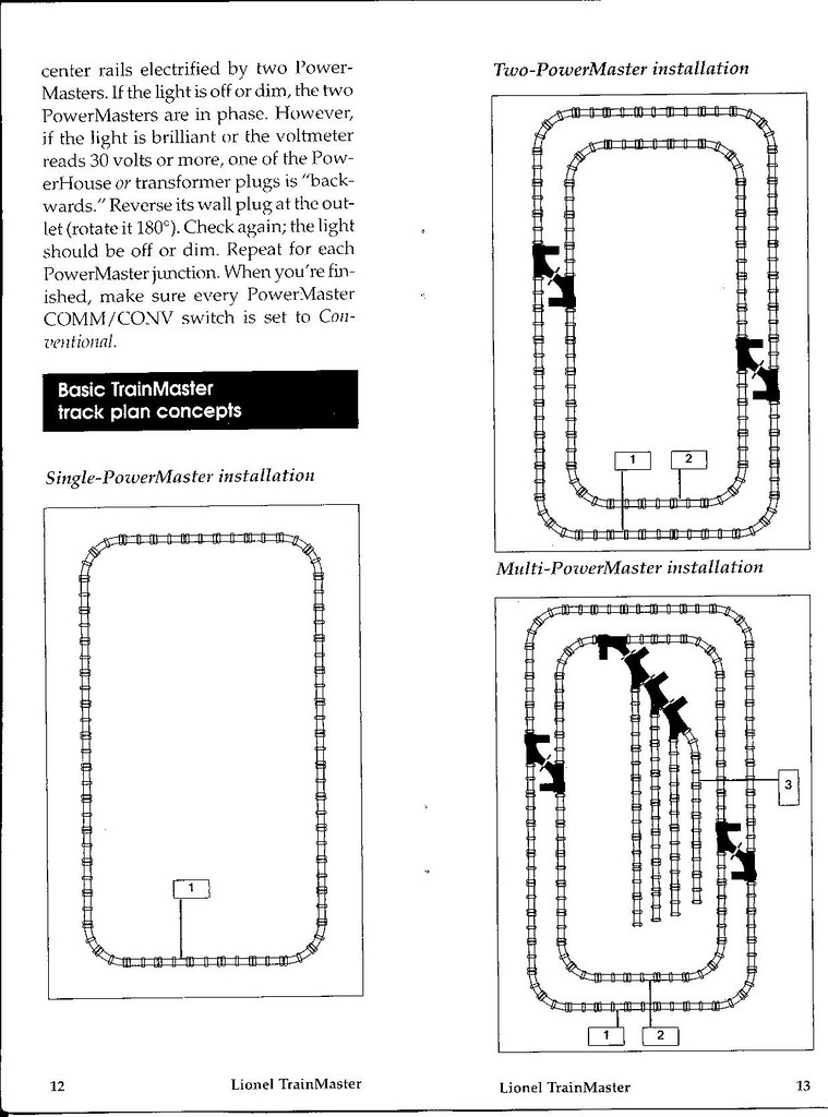
There is a similar layout in the ZW manual.
Quoting the ZW manual, dated January 1954:
“When crossing from one loop to another it is important that the voltages supplied to the inner and the outer loops are approximately equal.”
The circuit breaker in the ZW serves the common lead. I had to repair mine in 2003, as it was tripping at 4 to 5 amps. I think normal is 15 amps.