What switch machine do you anticipate using? I’m and HO guy and don’t know the N scale options.
I drilled large holes under my HO turnout throwbars, in case I wanted to use switch machines later. Of course the one I didn’t do, because a joist was precisely in the way, is the one I would really like to put a machine on now.
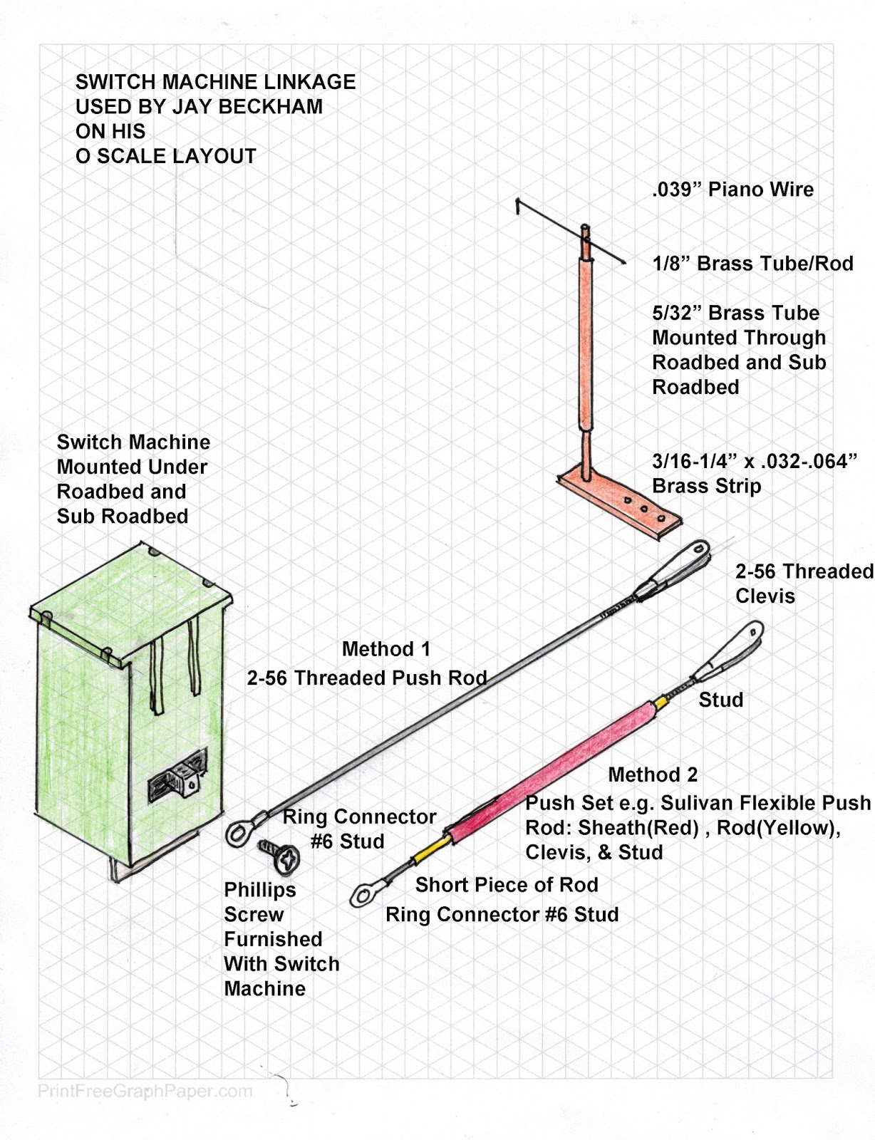
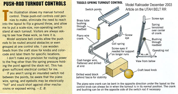
People have used a piece of piano wire attached the the end of the throwbar and run it through a tube (brass, styrene, or RC control sheath) to either a ground throw or a switch machine that is placed some distance to the side of the turnout. The tube runs only deep enough to be covered by scenicking material.
I was going to use Tortoise, but several weeks ago I saw some of Walthers system and it looked easier. It seem both machines are installed similarly. I’m not sure yet –
Like BigDaddy said above, I plan to control a number of my ‘unreachable’ turnouts with a very small diameter cable within a cable simply snaked along the surface of the deck and covered with grass/senery.
If it was me doing that I would pull the turnouts. I’m not very graceful and drilling a hole upwards to ½” in diameter from below would mean disaster for me. The turnout mechanisms are very delicate and the slightest problem will deem them unreliable.
The surface control rod would be a good alternative if removing the turnout would be a problem. A short surface linkage to a Tortoise would work very good too.
I haven’t ever used a control rod mechanism but I’m sure they would work as good or even better than an under table machine.
I didn’t even consider that as remotely feasible. If the layout were small enough to fit, upside down, under a drill press or a milling machine, it could work, but otherwise you are going to booger up the throw bar
Thanks for the input. I did find a forum page that someone told how they drilled a hole up, but at my age and my lack of experience, I think I would probably ruin everything.
I may try to figure out a surface solution like some of you suggest. I guess my last resort will be what Mel suggested and pull out the turnouts and go from there.
Circuitron makes a linkage to make the Tortoise more flexible, which could be used above ground or below. I used one to power a set of grade crossing gates.
I remember reading a thread some time ago and it addressed the very question you’re asking. They first drilled a small pilot hole from the top, then slid an NMRA gauge under the turnout (personally, I’d use a metal putty knife), then drill the final-sized hole from underneath.
I did it similar with successs. I did not drill the final hole but mill it from the bottom with the dremel. The mill in the dremel is easier to control than a drill.
using the approach shown below, you need to drill a hole close to the throwbar outside the track (not between the rails). It’s location doesn’t need to be precise. It size should allow a brass tube to fit snuggly but able to rotate.
bend a piece of wire (upside down J) that hooks into a hole on the top of the throwbar and solders into a brass tube that slides into the drilled hole (not as shown). drop it into the hole and hook it onto the throwbar.
an arm (1/4" sqaure stock) can be made with a vertical hole that slides onto the brass tube from the bottom and a threaded hole on the side that allows a screw to lock it onto the brass tube at any desired angle at one end and several holes for a wire at the other end.
attach the tortoise to the bottom of the layout, preferrably closer to the front of the layout. Attach a wire with a u-bend to the tortoise and the arm. the u-bend allows some adjustment.
It’s been a long time, and I’m not sure if anyone is even interested anymore.
I tried drilling up, with a putty knife under the turnout. It didn’t work. When I thought I was getting close, I actually was already pushing the putty knife up enough to ruin the turnout.
I replaced it. On the next one, I took the other suggestions and put the switch motor position off to the side of the turnout, and connected it to the turnout with a small piece of metal and plastic. Works like a charm.
I have more turnouts to do, and I will not again try to drill up. If I were younger, could control things better, and could see better, things might be different.
The trick to drilling up is to know the thickness of the structure, and you put a piece of tape around the drill bit such that slightly less than the needed length is exposed.
Count me in the camp for ruining a turnout for being too aggressive with drilling underneath one. Atlas turnouts are increasingly difficult to find, so knowing what your’re doing matters even more. Who wants to wait 2-4 weeks for a turnout?
It was annoying to work underneath the layout with a tortoise. Going through 2" of foam and feedeing the throw bar through the turnout hole was challenging.
Any thought to running a wire from the top of the turnout and attaching it to the switch machine underneath the layout? You could bend the wire 90 degrees to prevent it from sliding through the turnout. Another idea is using the wire as a “guide” of where to drill to create a larger hole for the Tortoise.
Got caught with the same problem- I drilled a small hole from the top down through the hole in the turnout. I then measured the thickness of the roadbed under the turnout. I used a spur wood drill bit (the bit has a small point that will follow the pilot hole) I used a wood shim under the turnout to raze it. Then I used a collar on the drill bit for correct depth. Then drilled from underneth. Go slow when the collar get close to the wood under the turnout. The wood shim will let the bit go through the road bed an not touch the turnout because of the collar.
look up a spur wood bit and you will see how clean a hole it will make.
I ended up using Walthers switch motors, about the same price as Tortoise. I really like the plug wiring and lights for fascia control without figuring anything out and without trying to solder connections under the table.
I actually ended up drilling through the table about ½ inch from the turnout bar. I installed the machine under the table, and connected the turnout bar to the switch machine’s wire with a small piece of plastic I rigged up. Filled in the hole except for the tiny opening for the machine wire sticking througn, painted it, and it works great and is nearly invisible.
Scenery stops you from reaching the turn out. Well that stops the discussion right there. Nothing else matters. First you must REMOVE the scenery so that you can access the turnout. {Be not afraid, for I have pulled many things up and have replaced them. Mre that 50% of the Route of the Broadway LION has been pulled up and replaced}
Having access to the turn out, I cut it out with a dremmel tool at the rail joiners. Remove the rail joiners from all rails. If the have been soldered, you will have to use a soldering Iron to remobe them.
MARK where you want the hole to be. A 1/4 inch hole is OK, but the LION uses a half inch hole, even in N scale noboyd is going to see it once things are put back together agqian. Undercut the sies on the switch, slide new rail joiners all the way onto the stock rails, and then place the switch and scootch the joiners back into place.
DISCARD the instructions from the Tortoise!. Use some tape to fix the switchpoints in mid throw. GENTLY move the actuator to mid-stroke.
Place a GLOB of Silicone caulk to the face of the Tortoise, keeping it away from the moving parts.
From the bottom of the table threzd the actuator through the hole in the throw bar, an