Placement: Assuming this would most likely be placed at a crossover track between two tracks, hence the “interlock” term?
Interior:
I wanted to leave the roof removable and have an interior for the second floor office. I see there are some kits for the interior for a bulding like this. I am guessing it would consist of desks, cabinets, and levers for throwing switches? How would these be placed in the interior? Assuming the stairways face the track, where would the levers for throwing turnouts go? Towards the window or back? Also assuming the number of levers would equal the number of turnouts this tower is responsible for managing?
Typically the stairways face away from the tracks.
The long axis would be parallel to the tracks.
Along the long axis of the building there would be a cabinet or row of levers to operate the signals, switches and derails in the interlocking. Above that there would be a model board that displays the layout of the interlocking and what the names/numbers of the components are. In the other parts there are desks, lockers, stove/heater, water cooler, etc.
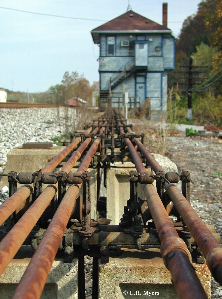
On the track side, at ground level there will be an opening as long as the row of levers or control cabinet where all the operating rods come out and go to the various components.
There are three types of interlocking machines, the lever type with a row of vertical levers each about 3-4 feet tall, the pistol grip type, with a cabinet about 3-4 feet tall and about 2 feet wide they a row of handles sticking out of the front (and a glass top) and then a modern electro mechanical with what looks like a CTC panel.
Search for “interlocking tower interior images” and you should hit lots of pictures.
I believe it is AMB and GC Laser that makes a laser-cut lever kit. Some railroads had a color code for the levers so I painted some white, blue, red or yellow depending on weather the lever controlled a lock, points signal or was out of service.
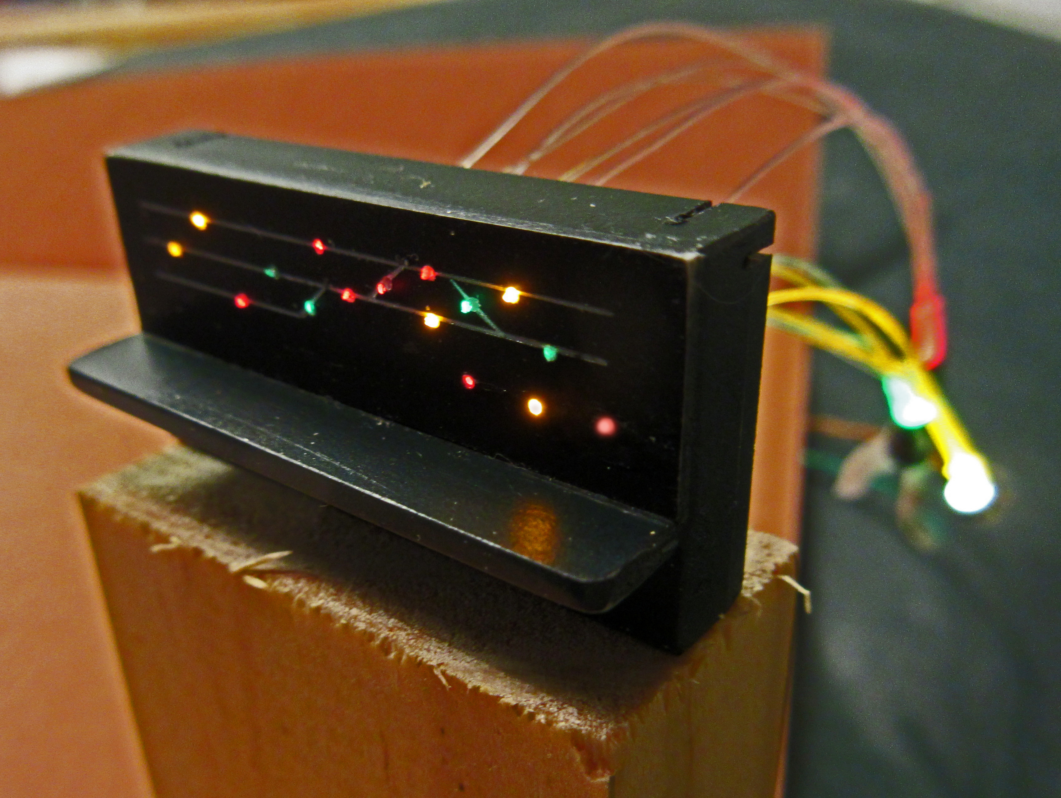
In this brick tower I modeled a later electro-pneumatic machine and I used colored fiber optics to represent pilot lights on the board.
Some great info and pictures (and modeling) here. Just a few thoughts about the interlocking tower I visited a few times in my youth. It was not a crossing, but it was an important junction on the C&NW where the two main lines from Chicago north met at St Francis Wisconsin, and the freight traffic basically went west and the passenger trains and a few freights continued north to the Allis or Marsh yards or the downtown depot (with some local freight switching on that line as well).
In addition to the operator’s desk and the interlocking plant (not Armstrong) which faced a panel (which had evidence of many many rearrangements of the track over the decades) with lights (there was also a bell to warn of trains enterring the plant’s area) what I remember were the walls. Hoops for hooping up orders were mounted on the wall, as was an enormous old red megaphone (basically a big cone) which I assume an operator could use to convey verbal messages to a train crewman over the noise of a locomotive or passing train. There were a number of old train bulletins framed and nailed to the wall and a variety of very old safety posters. Over the years the operators had also tacked photos they’d taken of passing trains or work crews. There were also some track tools here and there – the operator would not use them but they would be handy for quick borrowing by track crews who back in that day used to patrol pretty much all day on their Fairmont “speeder.” Interior lighting was VERY dim. There was a light at the top of the stairway to the second level.
The signal bridge with semaphore signals was very nearby the tower, on the line that saw the passenger service. It was a two track main with current of traffic rules but there were other tracks to allow meets and passes easily. If the operator needed to hoop up an order he’d do so near the tower’s base for the passenger line, but for that important line that we