How many independant circuits does the OP have within his layout room, anyway?
Normally in North America outlets (well, actually the circuit is) are rated for 15A, with heavier duty 20A outlets (normally having a ‘T’ shaped neutral) - again, this is 20A per circuit. This lighting scheme is some serious power draw, approaching stage lighting levels…
The 5050 LED strings draw 5 or 6 amps per 5 meters from a 12 volt source,so you’re looking at a load of 72 watts(plus a fraction for transformer loss) or less per strip. Roughly .6 amp(per strip)from your 120 volt outlet.
I’m getting a bit confused here. It is 72 watts or less per 5m strip, but as installed, these aren’t 5m strips. They’re cut to fit the layout section lengths, and the longest are 1.74m. Each power supply I’ve used has been 12v. There are three strips on each layout section, connected in parallel. I used 3 to eliminate shadows, especially against the backdrop.
Think of each 300 LED 5 meter strip as 100 groups of 3 leds.All the groups are wired in parallel,but the 3 LEDs in each group are wired in series. If 100 groups = 6 amps,then each group draws .06 amps. You can simply count the groups of three you have in your cut-to-length sections,and multiply by .06 to give you the amperage of that section.Do this with each section you have connected to the same power supply,and add those numbers together. That will give you the total amperage needed from that power supply. I like to size my power supplies above the amps needed by at least 25%. A power supply operating at less than maximum rated load runs cooler,and will likely last longer.
Mike
20 amps from a 12 volt source draws considerably less amperage from the 110 volt main in the conversion.
Mark.
You guys are confusing current and power. Power is watts, not amps. 20 amps at 12 volts is the same power as 2 amps at 120 volts.
shaking my head
Power is volts x amps, is it not? The desktop power supply I’ve got is 500W, and the mains AC voltage here in Australia is 240v. So, on the input side, from the power socket; 500/240 = 2.08A draw On the output side: 500/12 = 41.66A available. Is this correct? Will my approach of upgrading the wiring also work? Depending on how bright the lighting is, I may drop the middle strings.
Don’t use 240 to fiqure things use 220. Here in the states the real available power is closer to 109 vs. 120 rated. I have very little knowlege of low voltage so will bow out of the rest of the discusion.
Yes but that’s at 120 volts, 10x the voltage - so if all else were equal, 1/10th the amps. Even accounting for less than perfect power supplies, I’ll bet the draw at the wall is far less than your CFLs. 5 meters, 15+ feet, of LEDs drawing 5 amps, that would need to be just half an amp at 120V with CFLs - pretty sure enough CFLs to light up 15 feet of layout would draw more than 1/2 amp.
–Randy
The wiring is correct - you definitely want more than #28 wire for this! I’d run seperate bus runs to each section and fuse them off at something around the expected draw. If it’s 5 amps for 15 meters, that’s roughly 1 amp for every 3 meters. So just add up the length of all the strings you have connected to a given set of feeders and divide by 3 to figure how many amps you need to that group.
The breakout box is a good idea, that’s what I was going to do - so if the power supply went out, all I have to do is plug in another one. Beats cracking them open and making the mods - plus no worries about the high power caps inside which can give you quite a jolt even if the supply has been unplugged for hours. You’re a little optimistic on the draw from the wall, figure on basic computer power supplies running at about 80% efficiency, on a good day. So if you need 40 amps at 12V, 480 watts out, it will be more realistic to say it draws 600 watts from the wall, at 240VAC that’s 2.5 amps.
Based on what I’ve seen others do with similar widths, I figure I will need 3 strands on most of my layout, but I plan to make one of them an RGB strand so I can do daybreak/sunset/night effects as well as have it on full white with the other two for broad daylight.
&n
Taking into account the last few posts, on the input side have: 500w/220v = 2.27A current draw from power socket. On the output, we have 400w (80% of 500w) at 12v: 400w/12v = 33.34A available. Logging in total is 19.5A (approx), so this should be covered. I’m also thinking of breaking out another pair of connections with a 3A breaker, to power my accessory bus.
This is a bit complicated but yes and no.
INPUT SIDE:
First off power conversion isn’t 100% efficient. So you lose some of that conversion of 240VAC->12VDC to heat. So figure 85% efficiency conservatively (depending on how well the power supply is built and load). So you’re actually drawing closer to 2.08A / .85 = 2.44 Amps (If it’s a true 240 outlet and the power supply can handle 240V…most in the states are rated for 120/220 operation)
Now on the OUTPUT side:
Just because a power supply is rated at 500 Watts doesn’t mean it can deliver all 500 watts on a single 12V rail. That’s the combined power of all the rails. (3.3, 5, +12, -12 etc…) And a 12V rail pigtail (the cord that comes out of the box is a pig tail because it’s attached on) might be actually only rated to handle as low at 3 amps on a single rail.
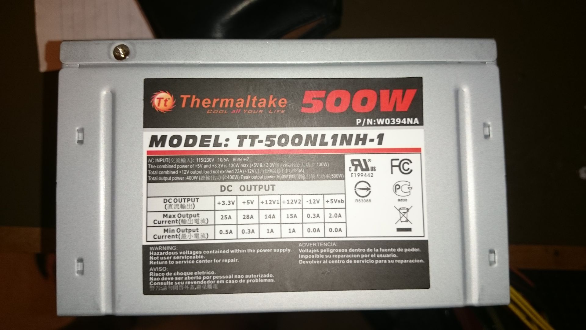
The real telling clue is to look at the label slapped on the side of 99% of quality power supplies which tells you the amp rating of each rail.
Didn’t know it was so complicated did ya?
The good news is even a mediocre quality 500Watt power supply should be enough lighting and power for accessories for a good size layout.
As a rule of
I’ve got the power supplies now, and it turns out that the 500W is actually the smaller of the two, the other being 600W. Both use the standard 20+4 ATX connector (with 2 12vDC rails), and both have an extra 4-pin plug with 12v DC output. I figure that if I build to the specifications of the 500W one, then I should be able to use both. The label for this one states that both 12v rails can handle up to 14A, although the combined total shouldn’t exceed 23A. With the figures rounded up (for a safety margin), section 1 of the layout will draw 6A, and the others all 4A. I will use the 4 pin 12vDC output to power the lighting for section 1, as this will put 3A over each wire in that plug. The other 4 sections (4A each) will come off the two power rails from the 20+4 pin connector - these will be carrying 8A each. This does mean that the 12v rail into which the 4-pin connector is attached will be running at 14A, but it can handle that. I’ll have to check how this connector is tied in to the 12v rails.
That should have been in 3 paragraphs. The forum seems to delete line breaks when I post from a mobile device ![]()
LION not so sure. Modern computer power supplies are switching supplies, which do require a load or they will not work. Put the load back and they should work.
OLDER supplies may have been regular transformer supplies that may not have required a load, or may have had a built in load on the assumption that a simple thing like a computer (sans all of those drives) did not draw wll that much power anyway.
Computer supplies are the same for USA and for Astralia-Europa,etc. since they have a little switch to select between one and the other, and the newer ones have not even that, they will take whatever you put into is and upt out the right stuff.
ROAR
The fact that it is a switching power supply does not mean it requires a load to work. It’s the design of said switching power supply. Most of the ones I’ve tried in realtively modern times (beyond Pentium III days) have turned on just fine under no load. The 12V side is usually a bit low, 11.5V or so, until a load is applied, and the 5V lines run about 5.03V, which drops under load (but that part is likely due to the nature of the supply which typically produces just 12V and the rest is all DC-DC converters making the lower voltages). Despite the voltages not being dead on (and even WITH load - they seldom are, just read any of the decent sites that review power supplies and actually chart the outputs under various loads, like HardOCP), they turned on just fine then connecting the proper lines, with nothing else attached to any of the connectors. Non-computer ones, if you look up the specs of ones solder by Mouser or Digi-Key, you will see some specify a minimum load and some say they do not need a load - all switching power supplies.
Old transformer supplies mostly went away by the PC-AT era. Those AST computers I was talking about that actually had a load resistor attached to the top of the power supply, or in the hard drive cage area, were definitely switching power supplies. The last computer I had that used a transformer and not a switching supply, hmm, I was thinking my TRS-80 Model 4P but I’m not so sure, I think it would have been a lot heavier with a big solid transformer in it. My DCC power supply is a simple transformer. My first computer has a BIG transformer supply with a physically huge main capacitor in it, and a row of TO-3 case voltage regulators arranged on a thick aluminum plate for a heat sink. It’s meant to allow the computer to be expanded, the basic system plus the expansion board I have draws maybe 2-3 amps total.
As for design - most 500 watt and under supplies are signle rail, only a few oddballs did multiple 12V rails in such a low power s
I’ve been looking at the power supply unit I’ve got (Thermaltake W0394), and I haven’t been able to find details on which power rails go to which outputs. I figure I have two options: - Put various 4A and the 6A feed on certain connectors, and hope that’s not overloading one of the 12v rails too much. - Take all of the +12v and ground connectors from the PSU and connect them up to two thick sections of wire, each of which is capable of carrying 25A. From these two wires, the feeds to the various lighting buses will be broken out. By connecting all the 12v and ground connectors in parallel like this, it would help distribute the total load. Would this work?
No, do not connect the rails in parallel. If there is no documentation on which connections go to which rails, you might be able to glean this insformation from the label. It should at lease indicate total capacity for each rail. If it’s a modular power supply, the 12V connection on the 20+4 motherboard connector will almost always be a different rail fromt he PCIE6/8 connections.
–Randy
Randy,
Below is the label of the power supply. It is literally all the information I’ve been able to find on the PSU:
These are the connectors coming off it:
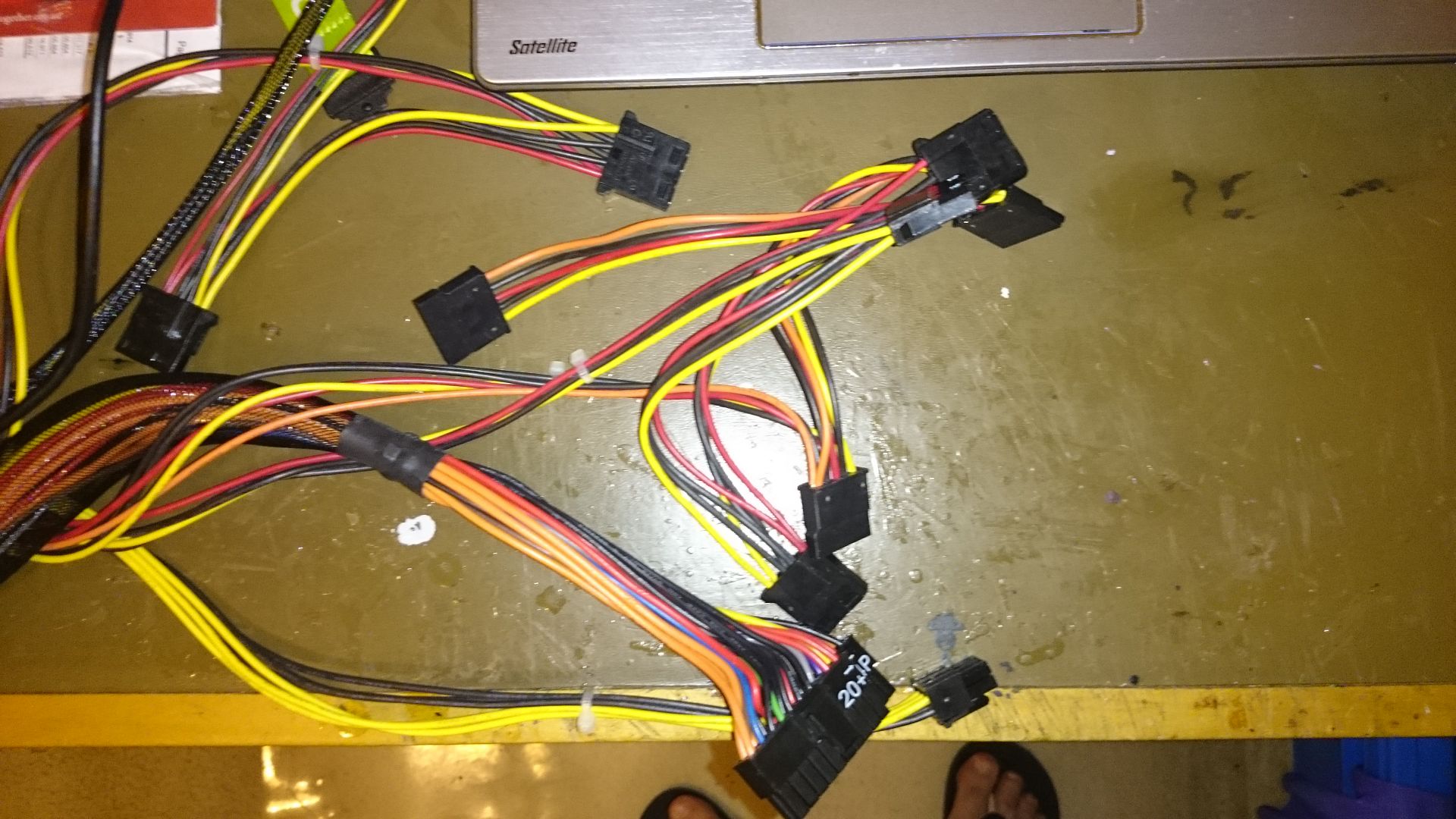
My main concern is that the connectors won’t be able to take the 12A current I’ll be pulling down them.
EDIT:
I have actually got a second PSU, which is used (as opposed to the unused one in the photo above). This is a Tauro XTK-TB-0600B, which has a single 12V rail capable of putting out up to 36A.
I’m guessing that this 36A output can’t be put over just the one connector, otherwise it’d melt the plugs. Given that this is the one rail, would connecting multiple plugs from it help to distribute the load?