I’m currently designing a layout to fit into half of a room in my basement. I’ll break down all the information and what specifically I’m looking for help on to try and make things easier.
The Specifics
Scale: HO (1:87)
Era: Modern
Type: Freelanced, set in southern WI (Union Pacific and WSOR featured)
Min. radius: 22" mainline, 18" sidings
Turnouts: No. 6 mainline, atlast snap switches for most sidings (already have them and plan to use them)
What I’m looking for in my layout: I’m trying for a layout that focuses almost entirely on way freights- freight comes in to the interchange yard and is distributed to various industries, and some freight from the layout goes back into “the rest of the world.” I’d especially like to focus on switching some related industries, switching in general, and yard work.
Rolling stock: 50’ boxcars, 2 53 or 57’ reefers, some 50’ flatcars, 40’ coal hoppers and 40’ gondolas, covered grain hoppers, 23,000 gallon tank cars.
Planned industries: bakery (major industry. hoppers and tanks in, reefers and boxcars out), gravel pit, cement works (gravel in, cement out), one or two team tracks for boxcars, a few freight interchange buildings, a coal power plant (coal comes in from the interchange yard) and a recycling plant that takes bales of scrap metal in and sends out metal coils.
A Note
I want the gravel quarry and cement works to be lower on the layout in relation to the yard (the yard being “ground level”) with slopes and trees as a viewblock, as well as using taller trees to hide how close the cement works is to the quarry. The black area in the picture is space I can’t build in, and the top foot of the layout can’t be built very high due to an overhanging bar. The layout also can’t exceed 10 feet by 10 feet. Also, in the picture, blue boxes are just indicators on where i’d like to place buildings. Some I have and don’t hav
A quick comment on the upper part of the plan where the freight and recycling facilities are: without a runaround track in this general area any trains made up in the yard will have to back all the way up to this area to drop cars. If you include a decent size runaround that will hold five or six cars a train made up in the yard can travel locomotive forward to the area and then break off for switching. Other than that I like the upper part of the plan.
On the lower part of the plan I don’t understand the crossover at the 5’ mark.
The lower part of the layout is 4’ deep. If it is located against a wall you won’t be able to reach to the back of the layout. If it is free standing with access from all sides you are good to go.
And lastly you’ve done a great job putting in enough trackage to make the layout interesting without jamming track into every available piece of real estate. This is a nice start for a switching layout!
XTrkCad, google it and you can find where to download it.
rfross- I forgot to mention, the bottom and left sides of the layout are open to the rest of the room (I just can’t build there). The crossover by the cement works is to try and add some interesting operations to moving gravel to the cement plant.
I think the last track in the cement plant is way too short, especially for a “switchback” move. I would make it at least 18" so both a locomotive and a car can fit instead of one or the other.
If the last track in the yard (lowest) is just a locomotive excape track, then I would make it parallel with the ladder instead of parallel with the yard tracks. If it is supposed to be a yard track it is too short and should just be eliminated.
While the crossing looks cool, to make it useful it needs to connect to the cement plant differently. Right now it connects to the shortest track and can’t really service the facility. When I first saw this I thought it was a grade thing so that empty cars could be gravity feed into the mine and full cars gravity feed out. This is what the D&RGW did at the Monarch dolomite mine. The mine did not require a loco to work the cars into and out of the tipples. So maybe instead of a crossing a bridge might be in order?
As a prior posted noted, I would put a run around track in the upper industrial area. That will allow you to take a train loco first out of the yard to the industrial area. Run around the train and work it into the industries. Then it can go loco first either back to the yard or to the cement plant. Likewise a train from the cement plant can go loco first to the upper part, turn and go into the yard loco first. Of course without a turntable or wye this layout almost dictates double sided power (GP60 or MP15?) unless one likes to run locomotives backwards.
This is my latest revision. The orange line is something i’m thinking about adding. I’d have a side track go down an incline into a tunnel to a hidden staging yard below the layout.
Sorry for such a late response, I was just catching up with my forum reading. Hopefully you haven’t already built the whole thing!
You said you would like some more length in the IC yard - if you pulled the first turnout back into the curve a bit and made it a RH instead of left, that would pull the whole ladder to the right and make each track maybe 6" longer.
As TZ said, the Gravel Pit yard tracks are too short, I would pull all that to the right 9-12".
The run-around you added in the upper area is a good thing.
Your orange track into a subterranean staging area would not only have to be awfully steep, it would be hard to make it plausible. You might try squeezing in a crossing between the first two down-facing turnouts and run this track along the right wall and behind the bakery, that would help hide it and also give you a bit more length to get down there; even at that, the grade would still be around 5% - still, it might be a good feature.
Overall, it’s shaping up to be a very nice switching layout for your objectives. Good luck!
You cheated on the turnarounds on both your interchanage track and gravel pit. Both are easily fixed. (I just noticed the one one the top as well. You’re going to have to learn how to make your track work on the program or it won’t work on the layout either.
The runaround at the grvel pit is the largest on the layout. It would be more importaant to have more trackage to the gravel pit istself. If yo use the interchange yard as the source and destination of all products on your layout, you can use that runaround if you need one.
You can get about 2 more feet on all your interchange tracks by using a rooster tail configureation. If you just run the yard ladder before you complete the turn, you’ll gain a foot.
You don’t have enough room got get below the table using the space you have shown with the orage arrow. Even a 4 % drop needs 8 feet just to clear the table. You can do it in your layout size. but you have to drop down and make a turn and run back under yourself. Figure 25’ of run before you get to your staging yard ladder.
It is good that you have placed your buildings on the layout. It shows you have space for them. But for the layout to make sense you need a road system, parking lots, room for trucks to back in to your freight facilities, etc.
Like others, I “don’t get” the “crossover” near the cement plant. I can’t see how it would have been built that way by a railroad. It does create a problem that might give some extra challenge for problem switching, but there are probably enough challenges in handling cars efficiently. Also, referring to the track arrangement as a “crossover” may be confusing because that is not standard railroad terminology. A crossover is found where there are two tracks side by side, often parallel, with a turnout on one track connecting to a turnout on the other where you can cross over from one line to the other. You have a crossing on your track plan near the cement works, with one track crossing another at grade. Sometimes a crossing at grade is called a diamond like the diamond shape on playing cards. The crossing you show would probably be rather rare on the prototype, might occur for some historical, legal or regulatory reason as tracks were built, and would probably be corrected as soon as practical.
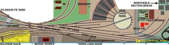
Here is a piece of the plan of the layout I am building that illustrates some of these points and terms.
Click to enlarge plan.
There is a CROSSING at the bottom of the plan where the spur to the barge works crosses the spur to the open load dock. This is an arrangement to squeeze 2 spurs and 2 industries into the space that about 1 1/2 would take without the crossing. This occasionally happens in congested switching districts, such as dockside.
The plan has two CROSSOVERS located next to each other. One crossover allows trains coming from the right on the ATSF main track to cross over to the ATSF yard lead to enter the yard. The curved side of a turnout is used for the crossover route on the ATSF yard lead track to avoid an S-curve. A train does not have to curve off the stra