I am installing a DCC decoder in an old style Athearn engine.I am going to install front and rear led lights.when installing a resistor which side of the led do I wire it to + or -,I assume the + side, and does it make a difference which way the current flows through the resistor?Thanks for any help.
Doesn’t matter which side of the LED, doesn’t matter which way it (the resistor) goes.
Good Luck!
I hook the resistor to the cathode side of the LED and the function output of the decoder. I hook the Anode side of the LED to the common side of the circuit. LED’s are directional. They are diodes and diodes control current flow. These particular diodes, LED’s, just emit light. Resistor current flow does not matter.
Here is a link to a not so great photo of how I set up a similar lighting arrangement in an engine I built.Scroll down the page toward the bottom.
http://www.dansresincasting.com/GE132%20ton%20PG4.htm
Dan Pikulski
I have been changing over all of my Athearn Genesis F units over to 3mm Golden White LED’s. What I’ve learned by trial and error is that you MUST put the resister on the longer of the two leads that come from the LED. If you put it on the shorter lead, it won’t work. LED’s are not light a 12v light bulb. With simple light bulbs, you can put the resister on either wire. With LED’s, this isn’t the case.
Michael
I must disagree. If that is happening there is something else going on in the circuit. It is absolutely true that the LED must be oriented correctly with respect to the supply, but which side the resistor is on is not important.
That’s some nice scratchbuilding Dan!
Joe
Nope - it absolutely does not matter which lead of the LED you put the resistor in, just so long as the resistor is between the LED and the wire to the decoder. And only 1 resistor, putting one on BOTH LED leads isn’t goig to do anything but take up more space.
What does matter is which LED lead hooks to the blue wire and which LED hooks to the function wire - the white, or yellow, or purple or green or whatever oddball colors they use when there are LOTS of functions - colors with stripes of some sort, but I haven’t used decoders with that many function wires. LEDs only work when current flows one way. The other way - it does not light. The good news is that if you DO connect it backwards, nothing will happen. As long as you didn;t forget the resistor, the worst that will happen is the LED won;t go on. Just flp the wires and all will be fine.
I have a degree in electrical engineering. I know intellectually which way an LED should be connected. I DO remember that the blue common wire is POSITIVE. Yet I usually end up with my LEDs in backwards [:D]. This is why I twist the wires on and test it before finally soldering the connections.
–Randy
I want to add some additional information regarding white or golden white LEDs:
-
Take care to verify the polarity before powering up the decoder. These LED’s are much more sensitive to reverse current than red, green or amber LED’s; in fact, the reverse current sensitivity varies according to the device’s light spectrum (some manufacturers now use a common white LED and TINT the casing in this case all LEDs in the series have the SAME characteristics).
-
Some DCC decoders leak the DCC signal through the effect/lighting output circuits; if you use a resistor value that biases the LED near the maximum rated current, it may fail after a short period of time. I have experienced this on several occasions. To avoid this, use a 1K (1000) ohm resistor or higher. For example Miniatronics LEDs ship with 270 ohm and 470 ohm resistors; the 270 ohm resistors are recommended by Miniatronics for low voltage DC use (4-9 Volts). They recommend the 470 ohm resistors for 10-16 Volts DC. I do not recommend using these resistors for DCC installations. Because the ratio of light output to current applied is not linear, any resistor value between 1K and 2.2K will work well for DCC.
-
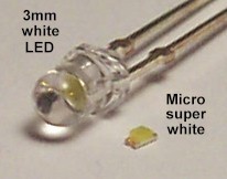
Modeling TIP: if you are looking for LEDs smaller than 3mm, try the micro and nano size LEDs from Ngineering http://www.ngineering.com . The light output is outstanding; don’t judge them by their size, the output is brighter and full as compared to incandescent bulbs of the same dimensions.
Atlas uses LEDs of this type in the new SDP-35 locomotive for headlights.
Those surface-mount LEDs are great - you cna now put lighs in palces previously not possible, like right in a ditch light casting, no crazy fiber optics. Or even have a true twin sealed beam headlight. But they are TINY and probably not something a newcomer to soldering should fool with. You need to use some VERY fine wiere - even the usual decoder wire is actually bigger than the LED. Enamel insulated magnet wire is recommended. A magnifier to work under would be a good idea, even for younger eyes. Paste solder helps. These kinds of devices were never meant to be soldered by hand using a soldering iron in the usual fashion. In their actual use in comemrcial products, they are stuck to the boards with paste solder and the entre circuit board is heated to flow the solder. You CAN do these by hand, it just takes a very careful and delicate touch. See the article from, hmm, about a year ago in RMC on making caboose marker lights. SCALE SIZE marker lights, not oversize to accomodate a light bulb.
–Randy
Revhack: You have received some excellent info from Randy, so I am not going to repeat. I noticed that you also asked about direction of resistors, and others have answered that correctly also, however, I want to give you a visual ( in your mind) of what a resistor does, in laymans language, that hopefully will help you with other electrical questions that will arise down the road.
Think of a circuit as a length of pipe that has various components attached. Lets say that this particular circuit is made of 1" diameter pipe to carry sufficient current. Now, we come to a component that is not going to be happy with the amount of current that is going to flow through it. What we do, is to install a 1/2" diameter pipe to restrict the current flow. That 1/2" piece of pipe is called…you guessed it…a “resistor”. As you can see, it makes no difference at all which way the current flows through this resistor, it will restrict the flow either way.
I must point out that what DOES matter, is WHERE you place the resistor. In your case, you want to restrict the current, and also drop the voltage to the Decoder so that you don’t blow it.
There is a GREAT Explanation of LED’s, how they work and how to wire them up from someone who we all will agree is a pretty reliable sourse…Tony’s Trains…
Check it out for yourself…
Installing LEDs with DCC Decoders | Tech News at Tony’s Train Exchange.
Thanks everyone for all the helpfull info.I have the decoder wired, now I’ll be able to install the lights.
Rev