I’ll take your work for the gap. Check to see if the voltage across the LEDs are the same. If not you must have a problem with the individual LEDs. All the LEDs from the same batch should draw the same current or be very close. I wouldn’t expect more than ±0.1 volts variation when measured across the LEDs.
Give me a break Greg, I was speaking individually they should be very close and the voltage across each LED in series should be within ± 0.1 measuring each LED.
Sorry Brent for not being exact. I always expect everyone to understand what I’m trying to say, that’s what happens when you get old as dirt.
Okay, I finally made it to the trainroom, with the probe either side of each individual LED on the copper tape, here’s the poop. Left to right, brightest light next to the resistor.
And where did you get them? I would look for a different supplier. They should be very close, those are not.
If I was going to use them I’d use a separate resistor in series with each LED, you will have to dink around with the resistors to get the brightness equal.
I just tried 6 random wide angle LEDs out of my LED stock in series with my bench power supply at 10ma and all 6 looked the same brightness to me. I didn’t check the voltage but they were close enough for me by eye.
Do you think it could have something to do with my crappy soldering? They were my first efforts, the bright light was much later in production. I did get much better after about twenty of them.
No, if you had soldering problems in series it would effect all of the LEDs. The only problem soldering in series would be added resistance between the legs on the LEDs. If there is something next to the LED terminals that could add in some resistance parallel to each LED that would account for the difference in brightness.
I don’t run my LEDs in series. I use a 5 volt power supply for the LEDs on my layout and 4 volts in my passenger cars and cabooses with individual resistors in series with each LED. I rarely run them higher than a few ma each, under 2 ma in my passenger cars.
I’m a incandescent guy for my structure lighting. My Korber Roundhouse has fifteen 12 volt 70 ma Grain of Wheat bulbs operating at 8½ volts. I’ve never had a 12 volt Grain of Wheat bulb operating at 8½ volts burn out in almost 30 years.
I’ve never worried about the higher current draw from incandescent bulbs on my layout. My current draw at 8½ volts is less then 70 watts, most people waste more power than 70 watts just forgetting to turn off a light in their house a few time a month.
As Mel suggested, there shouldn’t be that much variance in the voltage across the LEDs. I suspect that the LEDs are themselves the culprit. Where did you get them?
I have two suggestions:
Buy some new LEDs from a source that you can trust. ‘Wehonest’ on eBay usually receives favourable comments on the forums.
Forget wiring the LEDs four in series with one resistor. Use a resistor for each LED. Tried and true. Sorry to repeat myself, but if you are like me and don’t understand the intricacies of electronics, then do what works.
I think the overheating might have been an issue as I was having trouble with the early ones. When I switched from liquid flux to a paste, the paste helped hold the magnet wire in place and I was in and out fast.
What if there is some residual paste on the LED causing a shorting issue, is that possible?
I think I am going to hang some of my later efforts and see if that solves the problem.
What temp should I use to solder the resistors to the copper tape? It seems to take longer for the solder to bond with the resistor than the copper tape even though I am tinning the resistor.
Because the foil is so thin it absorbs the heat from the soldering iron quicker than the resistor. Tin and put a small blob of solder on the resistor and apply the heated portion of the resistor lead to the foil. In and out quickly. I normally operate my iron at 750°.
I have run into soldering paste that had leakage but never enough to cause this problem. I’ve been working with LEDs since they became available and never had one change value or get dimmer or brighter from a soldering iron. They have either worked normal or quit as in dead.
I would have to say the manufacturing process failed or they weren’t from the same batch before you received them.
Like Dave said try them individually each with its own resistor. Individually the brightness might be close enough that it isn’t as noticeable. I series they will float at different level of light but might be forced using their own resistor.
could it be the twisted magnet wire? soldering the wires may have softened the insulation.
can you try unsoldering one leg of the dimmest LED
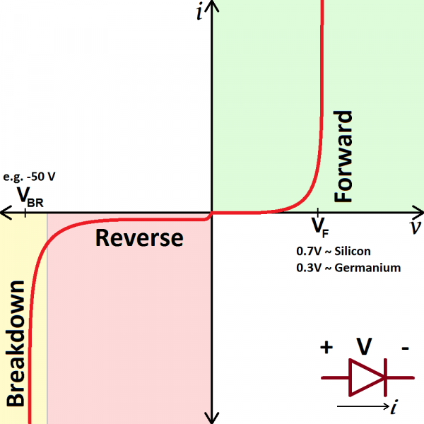
Measure the resistance from the ends of the wire where they are soldered in both directions. in one direction, the forward diode direction, it should be low, in the opposite direction it should be infinite. If it’s not infinite, then there’s a resistive path in parallel with the LED.
try to separate the twisted magnet wires all the way to the LED. See if the resistance become infinite
after separating, see if it is brighter by holding the unsoldered end against the solder pad
Okay, after a quick visit back to my array, I may have had the ultimate DUH! moment. I have four SMD603s in a series, they are rated at 20ma forward each. Does this affect the other LEDs downstream? Also, the #38 Magnet wire is rated at 35ma.[D)] I somehow had referenced a different package of wire I had. So am I right in assuming that either or both is the problem?[:$]
No, and the current rating has nothing to do with it. The current rating of an LED is the maximum you can allow through it before it becomes a DED (dark emitting diode). The key parameter for series wiring LEDs is the forward voltage. If the rating is 3.5 volts, and you put 4x in series, the total voltage is 4 x 3.5, 14 volts. You will need a poer supply that puts out more than this. To calculate the current and resistor needed, simply treat the 4 LEDs as one, so now you have a 14V LED. Say you feed it with 16V. For a single LED, you take Vpowersupply and subtract Vled, and use this result and the desired current to calculate the resistor via Ohm’s law, solving for R, so R=V/I. I should NEVER be the maximum from the LED rating, and definitely not over it. So we want half, 10ma - so you have your 16V power supply, 14V dropped across the 4 LEDs, leaving 2 volts, divided by 10ma (.010 amps) and you get a 200 ohm resistor. 200 ohms is only a standard value in 5% tolerance which isn’t all that common. So you will have to go a little bit larger, for less current, or a little bit smaller, for more current. Either way, since we calculated at 10ma, you have plenty of room to go one size smaller resistor without exceeding the 20ma. For slightly less brightness, use the nearest higher value resistor, for lower current.
Really that’s all there is to it. If the LEDs are all matched, with the same forward voltages, then there should be no difference in brightness as each one will drop the same voltage, and the exact same current will flow through each of the 5 devices in series (4 LEDs and the resistor).
As Randy said “current isn’t the problem” and has nothing to do with it.
Is the difference in brightness disturbing? If not go with them. If it is disturbing then I would suggest you start over with matched LEDs, all from the same batch. From what you have described the LEDs you are using are not matched. They will work individually with their own resistor, you will most likely have to dink around with the resistor values to make them perfectly matched for brightness.
I personally wouldn’t use SMD LEDs in a structure, to much trouble as well as undesirable light dispersion. If size is the issue then go with the 1.8mm stovepipe LEDs and chop off the top, you would get more evenly dispersed light as well as more light per ma.
I use 3mm wide angle LEDs for interior lighting in my passenger cars and incandescent Grain of Wheat bulbs in my structures. The wide angle LEDs would work much better in structures than the SMD or stovepipe.
In the first post showing what the array wizard showed, the last line at the bottom says “the array draws a current of 140mA from the source”. What size wire should I be using to attach to the LEDs?
Not for a single 20ma string. I would use a heaver buss for the main feeder. I run minimum of #22 (920ma) for my lighting, #20 (1.5A) twisted pair (bell wire) is my normal lighting and turnout switch machine wiring.
I wouldn’t run any LEDs at max current. Like I said in an earlier post I rarely run any LED over 10ma, most under 2ma. I have a few SMD LEDs, none over 1ma, they’re too bright at 2ma for my lanterns.
These 3mm LED table lamps are running .5ma each.
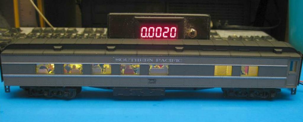
The car below has a total of 8 LEDs and the meter is reading the total current at 4 volts, 2ma.