-
Okay, I get that it will blink on and off 60 times a second. But can you tell? Will it send an autistic person into seizures?
-
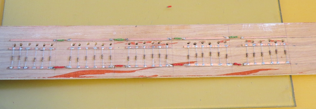
Can you run LEDs and grain of rice bulbs in parallel off the same circuit. (Without the resistors.) Here’s the LED part.
Okay, I get that it will blink on and off 60 times a second. But can you tell? Will it send an autistic person into seizures?
Can you run LEDs and grain of rice bulbs in parallel off the same circuit. (Without the resistors.) Here’s the LED part.
the intensity of LEDs is often controlled using a PWM signal, turning it on an off quickly. you would use half the resistor value for the same intensity if only driven half the time. if you have multiple LEDs to drive, connect two to the same resistor but with one with opposite polarity
you should be able to use the same AC source for LEDS wired above and incandescent bulbs with the appropriate voltage rating
Granted you are talking to someone who gets the heebee-geebees when you start talking Ohm’s Law, but this doesn’t make sense to me.
The current is either going the right way or it isn’t. It seems the resistance would still be the same.
On the otherhand, using the same resistor for two LEDs and cross wiring them does make sense, because one will be getting juice while the other isn’t.
On the other hand, and it might be slightly overkill, I have an 800W computer power supply that delivers 12V DC.
You could use a single bridge rectifier for a single LED bus with multiple LEDs. The LEDs will now pulse at 120 Hz, since you are giving them full wave rectification, not half.
Okay, I guess I’m getting an education. If I understand Professor Google correctly, a single bridge rectifier effectively converts AC to DC.
If I had one, that would be great, but for the cost of 5 with free shipping, or one if I pay shipping, I can get two 12V DC power supplies from Amazon.
you can also use a diode, either single or in two, to convert AC to DC, it’s easier on the LED I think … plus a dropping resistor in line … from 12 volt to the two to three that your LED will use …
a diode or resistor is only a few cents
I already have a bus with 30 LEDs pre-wired in parallel.
I guess that is why everyone seems to use 12vdc for accessories. Much easier to deal with.
My NCE Power Cab has a 3mm red LED and 1k resistor tied to the output to indivate DCC, a form of AC and does not blink.
Make sure you have fuses with that much power from a computer power supply. I know what those are capable of.
There are online companies that are much cheaper than Amazon for parts.
Rich
What he means is this: imagine there are two LEDs in parallel, hooked up so they are opposite in polarity. They share a common resistor. Since a LED is a diode, when one conducts, the other doesn’t, so they can happily share that one resustor.
Now feed it 60-cycle AC. First one diode lights, then 1/120 of a second later it goes off and the other lights up, and they go on alternating 60 times a second each. But the only electricity going through the resistor is that which is going through whichever diode is on at the moment.
I don’t quite get this. All a diode will do is turn AC into half-wave DC … but your LED does exactly the same thing anyway; that’s what the D in LED is there for. If the half-wave DC has correct polarity for the LED it will light exactly as it does on AC; if it is opposed, the LED will never light up. No matter how ‘cheap’ you get a diode, that doesn’t add anything.
Diodes in a bridge rectifier have the effect of reversing the polarity of every half-wave of the AC, so it turns into DC with ripple at 120Hz. You can smooth this with a proper LC circuit (where the cap evens the voltage and the inductor evens the current) to get rid of any visible on-off flickering, but you may still notice 120hz brightening or dimming – most people don’t find that objectionable.
One fun thing you can do is see the effect of persistence of vision with an LED running on AC (or better yet an LED digital clock with matrix drive) – light it up in the dark and then quickly wave it or move your head…
That’s not the part I had trouble with.
The part I had trouble with is that Greg said since with AC, the current switches the LED on only when it is flowing in the right direction, it is only on half the time, so it only needs half the resistance.
It seems to me, the LED is either on or off even if it’s only for 1/60th of a second. It would still need full resistance.
He’s probably right. I just can see how.
I guess my point would be, since I have worked with LED’s since 1972, I would never try that. Always used DC. What I was taught.
Rich
Well all the LED’s need a resistor for its self. I have used LED’s on DCC using just the rail power with a resistor to the LED On one leg. I can’t see any flicker of the LED. USED on loco’s all the time with DCC for H/L.
Rich, SURELY you do not think that nearly 30V rail-to-rail DCC power is going out to your track in series with that single 3mm LED, do you? [(-D][(-D][(-D]
I was semi-joking. There are better ways to handle it.
I usually get most of the stuff on eBay, and it’s dirt cheap if you can wait for the Chinese junk to sail here. I tried a few online dealers, but with shipping the price was comparable to Amazon.
What sealed the deal for me is that I am in the process of getting the layout ready for track. I wanted to prewire the Atlas turntable when I cut the plywood to drop it in, even though I won’t convert to a wooden bridge turntable for a while. That’s when I noticed that the LEDs were hooked up to AC. I wired them for 12V DC.
I want to close up the top of the layout so I can get the roadbed down. Amazon will get me parts in one day.
The LED on the panel is wired across Rail A and Rail B, with a resistor - so it ‘sees’ the track voltage. Half the time, anyway - in the opposite half of the DCC wave, it doesn;t allow any current flow.
Rail to rail isn’t 30V - it’s typically around 15V. One way to measure track voltage without a special meter is to measure Rail A to common, and Rail B to common, then add them.
A red LED is ok, as long as it has a resistor - but LEDs in general have fairly low reverse voltage limits. Whereas many regular silicon diodes can withstand 50, 100, 200, 400, or even more volts in the reverse direction before breaking down, LEDs are typically much lower. Typical red LEDs are generally OK, but a lot of white LEDs can be damaged by a reverse voltage no more than their actual forward voltage.
Chip - it’s like this. If running the LED on DC, the power is always in the direction that lights the LED. 100% of the time. So the LED is whatever brightness it is based on the amount of current - controlled by the resistor. If instead of being on 100% of the time, you feed it AC, the LED now is only lit up half the time. All else being equal, it will appear half as bright. You cna compensate by using a lower value resistor, so when the LED is on, it’s a brighter ‘on’, raising the average brightness.
–Randy
[bow][bow][bow]
I thought DCC spec was at least 14V either plus or minus (measured from the respective rail to common) with the modulation arranged as on old modems to keep the net electron charge transfer equalized. That by definition would give you not less than 28V rail-to-rail of the power supply, were you able to get inside and measure it. If the actual modulation of the ‘square wave’ signal is only ~7V, which as I recall is around where some sound chips become active, I’d be MUCH less surprised why even small booboos in track lead to functional dropouts…
half the resistance means twice the current. but if it’s only on half the time, the power (Watts) and intensity are halved. in other words, ~same intensity as with DC when using half the resistance and AC
that’s too bad.
i had suggested that you could wire 2 LEDs in parallel with reversed polarity. this would cut the number of resistors in half, as well address some peoples concern that you should wire a reversed biased diode to limit the reverse voltage across the LED.
but if you’re using 12V, you could also wire 2 or more LEDs in series, further cutting the number of resistors. this may be helpful if you need to replace the resistors.