Does the Lionel 167 whistle controller give an extra boost to the track as a transformer controller doer? I have a 6-5906 sound activator and it does not.
I’d have to guess not. Do you want to know a way to rig up a suitable system to do so?
1 Like
Yes,if you don’t mind taking the time to explain what all is involved. I’m not sure I’d actually attempt it,but I might.
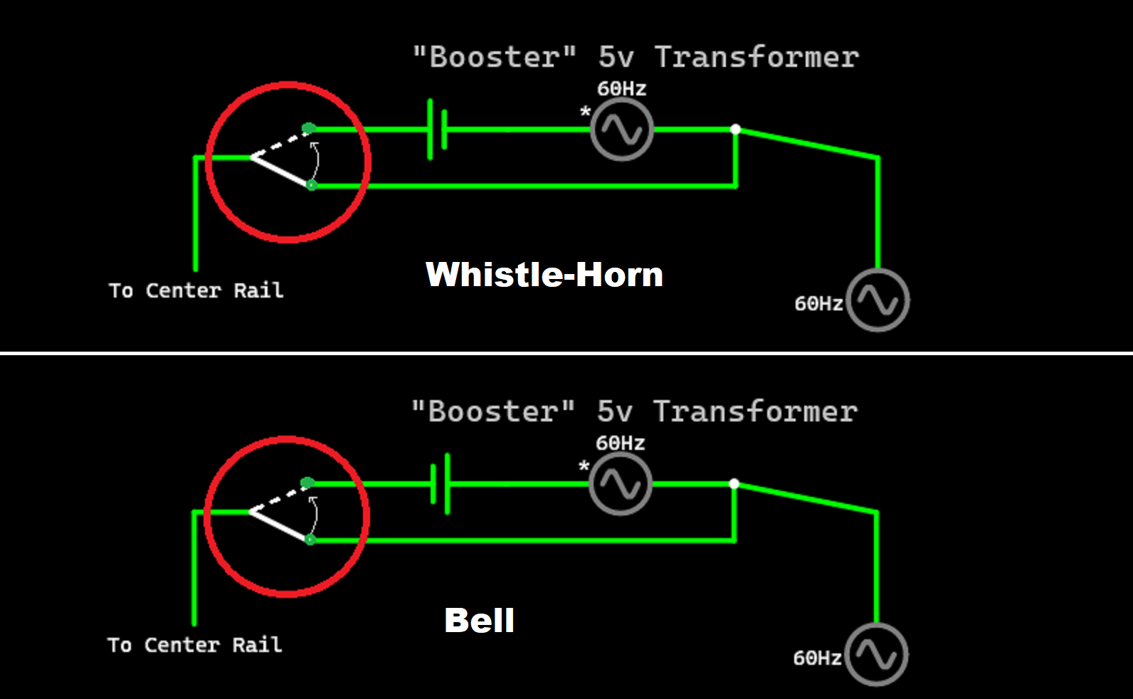
It’s immensely simple: just wire up this circuit!
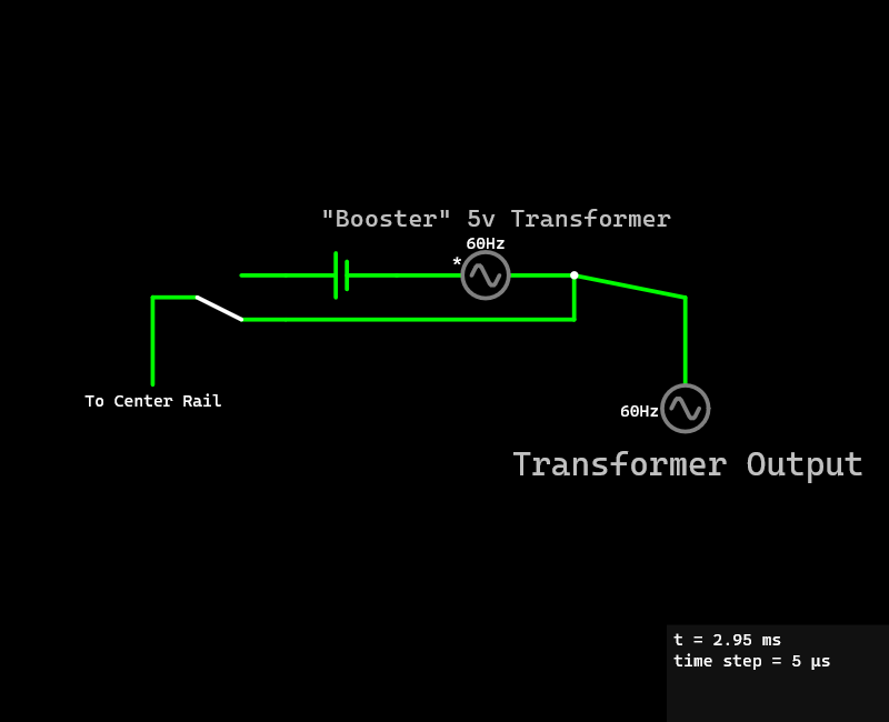
It’s most effective if you can find a pushbutton SPDT switch that has a normally closed and normally open position, but those aren’t always easy to come by. If you can’t find one, then you can use a regular maintained SPDT without center off. The whistle itself is actually controlled by the battery. The small booster transformer can be darn near any transformer with a 5v output (a 1033 would work, for example). But here it is strictly necessary that it be in phase with the main transformer. It would be possible to use the same transformer for both functions, but that depends upon which one you are using, specifically. Note that if it doesn’t make the whistle blow, turn the battery around (I can never remember the polarity, anyway). If you have any locomotives with bells, you can make two of these and have one for bells and the other for whistles. The polarity between the two will have to be different.
1 Like
Engine_1988
I have some questions about the information you provided. I have a few Lionel push buttons from the past which I used to activate uncouplers or operating cars. Are these the type of button you are talking about? Otherwise I have a DPDT switch. Second, I do not see in the diagram where the switch fits in. Third, if I were to use a 1033 for the 5v transformer, to which terminal would I attach the hot wire of the primary transformer and to which terminal the battery? Finally(for now anyway), what type of battery should be used?
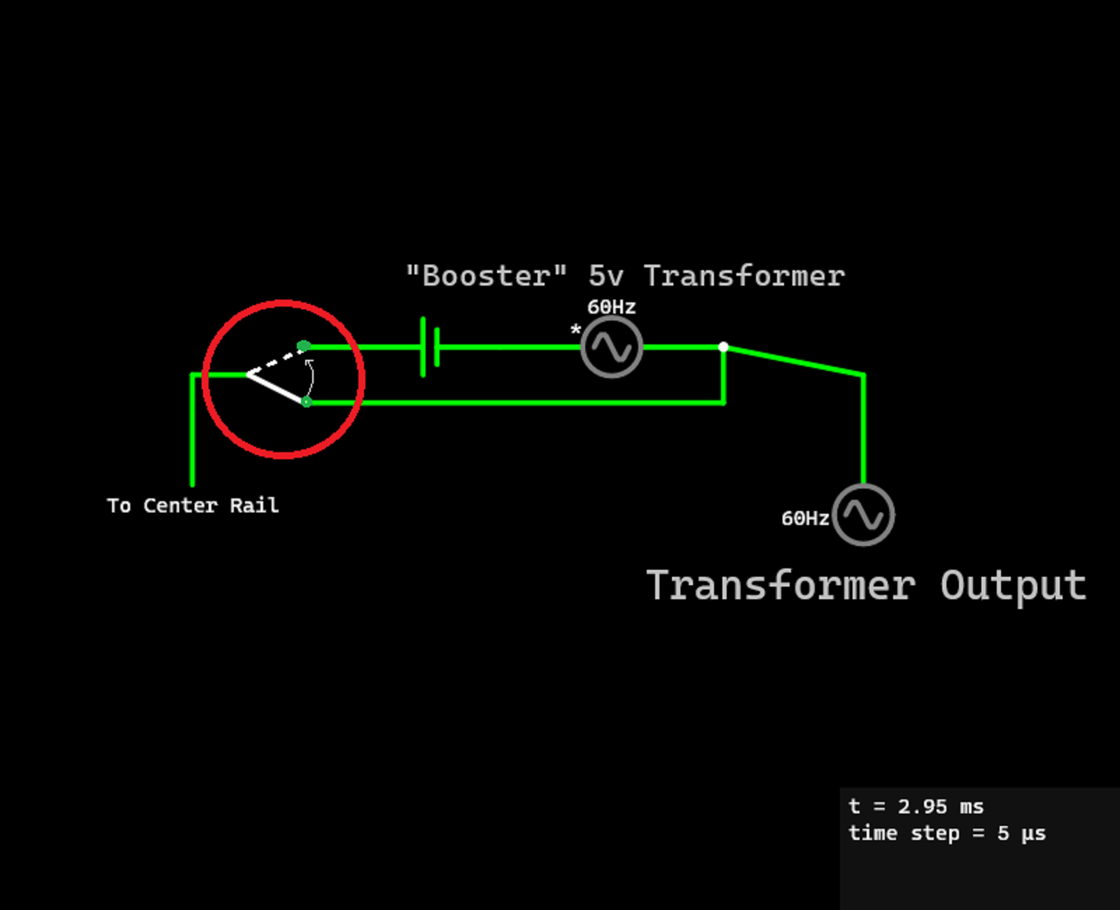
No, I’m not referring to the Lionel pushbuttons. Those definitely will not work (it probably could be rigged up to work, but is likely not worth the trouble). The DPDT switch could work, but it needs to NOT have a center off position. Switches like these are optimal: WMYCONGCONG 15 PCS SPDT Momentary Push Button Switch 3 Pin AC 2A 250V/ 5A 120V NO/NC: Amazon.com: Industrial & Scientific, but if you don’t have them then you’ll have to buy them. The switch itself, in the diagram, is the white line. Using the 1033, you would want to hook up A to the primary transformer and B to the battery. The transformer has to be in phase with your primary transformer. As for the battery itself, a D cell works quite well but really any 1.5v battery will work. Oh, and the battery may not be quite enough to activate some whistles (especially if they haven’t been serviced in a while), so you could quite easily use two batteries in series instead of one battery.
1 Like
Thanks again. That clears up a lot. I will probably wait until after the holidays to order the button. I really miss Radio Shack where I could likely buy just one or a few. This sounds like a really neat project and something I can actually do. One last question and then I’ll be ready to give it a try once I get the button. How do you wire the three pronged button?
I do wish that Radio Shack was around, too. Anyway, since there’s no diagram on the Amazon page, you’re on your own! Not really. This is pretty simple. What you need to do is “map” the switch’s contacts. Here’s how to do it, easily. First, select a side of the switch. These appear to have lettering on only one side, so choose the one with no lettering. Next, draw a loose diagram of that side. It can be no more, if you want, than a simple box with the three terminals sticking out of the bottom. Now you need to start a legend denotation on your diagram. A short ways away from the drawing of the switch, write with a colored pencil (for example, green) “Normally Closed”. Then write with a different colored pencil (for example, red) “Normally Open”. Next, get a multimeter. Mine has a continuity tester setting, but if yours doesn’t then use one of the various resistance tester settings. Next, test the resistance between each of the terminals on the switch. Check each of them, twice. Or thrice. I’ve learned the hard way. If you find terminals that have a low resistance (or make the continuity tester beep), then draw a line with the green-colored pencil between those in your diagram. There should only be one such line. Then, holding down the button, test all the terminals again. Draw the line this time with the red pencil. There should now be two lines on the diagram. The terminal that the two lines meet at is the common terminal. It should be connected the the center rail. The other terminal that the green line goes to is the Normally Closed terminal. It should be connected directly to the output of your primary transformer. The third terminal is the Normally Open terminal. It should be connected to the battery, like is shown in the electrical diagram.
This is by no means the simplest or fastest way to figure out how to wire one of these switches, but it is the only one that works for almost all switches–not just SPDT pushbuttons. Plus, it’s mostly foolproof, which is why I use it–I am a fool!
1 Like
Thank you again for your time and your help.
You’re welcome!
1 Like
Note that this circuit they have does not boost the voltage like the one I recommended.
1 Like
Hello Engine_1988. I’ve got the button ordered and my D cell(s) ready to go. I do have one more question(for now). On your diagram there seems to be a wire coming out of the battery on the opposite side of the booster transformer but leading nowhere. Is this correct or is that wire supposed to connect to something?
Thank you, Rob.
1 Like
Thanks again. On the topic of whistles (Lionel postwar). I have four or five which I have in as good a working order as I can(I.e. new brushes when needed, cleaned the armature, etc.) but l have noticed that there is a great difference among various postwar engines pulling a given tender(at different times, of course) as to which, engine or tender, receives the greater power. One engine might be brought almost to a standstill while another will remain at practically at the same running speed. I am curios as to why this is. By the way, these trial runs occur using the same transformer.
The key here is that they draw only the power they need, there is no division. If a tender whistle motor draws more power than a different one, it would point to a detailed clean/lube job needed.
3 Likes
So the engine that is less affected by the blowing of the whistle needs less power than the one which is brought nearly to a halt?