This is my first posting. I’m working on a plan for an approx 15’ x 20’ layout, my third. It will be almost entirely urban, and while not totally prototypical, I don’t want to do anything completely unprototypical. I was reading Jeff Wilson’s book on junctions. Figure 1-10 suggested a way to model a very limited interchange. I don’t have room at the moment on my plan for a junction. I can model an interchange track running from my mainline through the backdrop and into staging. This will suggest the real junction is “down the track.” There but not to be seen.
My question–do junctions and the interchange track(s) on prototypes get located in urban areas? Or, are they located outside of town?
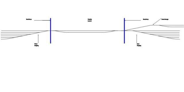
I’m including a schematic of the track plan. Visable layout is in the middle. Staging at each end. Interchange in upper right. Blue lines represent the backdrop.
Interchanges are located wherever the railroads cross. They can cross anyplace. If you look at a city like Chicago, Kansas City or St Louis there are dozens of interchanges.
for the most part we usually deivered cars to foreign road by taking them to that road’s yard and leaving them in a track destignated by their yardmaster. same thing in reverse when they deivered to us, they would report how many cars they had for us and call for a track when they were ready to make the delivery.
some roads had designated interchange tracks for this purpose and others just used the most convenient clear track.
I agree with grizlump’s first line, but usually the class I yardmasters I worked with would tell us where our outbound interchange was located, and we would pick it up afrer cutting off his inbound on the designated track, and running around the rest of the yard tracks, usually on the main. This would lead me to suggest you have a double-ended track with room to get your engines free to return to the west (left) end of your I/C yard and back in to pick up your outboud train from its track.
Look at Shomo Yard, Hagertown, MD on Mapquest, or whichever tool you use, for an example of an urban yard used for I/C… JWH
What you are thinking about is pretty much what I am trying to do so maybe some of my ideas will help.
Let me first say that I switched from home/UK profile to American interest about 20 years ago so my research, planning and modelling has been based on “distance learning”. Mind you, I have leant a vast amount here. [tup]
Anyway…
RR are fairly rarely set down in urban or even semi-urban locations… what does frequenttly happen is that a RR or RRs arrive and then development occurs around them. In many cases the development will initially be various industries that want good rail access right up close to the tracks. Over years the industries themselves may add tracks or it may be necessary to add spurs to reach through the first layer of industry next to the track to a second and any other subsequent layers further back. These spurs can remain in the ownership of the original RR(s), be owned by the industry/industries or, sometimes, become a small RR company in their own right. They can be small “spaghetti bowl” like complexes all squashed in to an area and serving a lot of relatively small facilities or a long, strung out vine serving all sorts of facilities. (One place to search the net for the former is “Chicago Switching”).
Times change. Among other things that happen industries switch to using trucks. This can mean that the up-close industrial buidings close and fence or wall off their one time RR docks. Track may be left out of use, concreted or tarmaced over or ripped out. Track left in may have it’s connecting switch removed while, at the other extreme, track ripped out may still have the switch in place. Sometimes the blades of a switch are taken out and straight rail substituted. Sometimes the common crossing (frog) is also replaced with plain rail. In either case the switch ties at least may remain for some years until they individually need replacing or the whole lot get chang
And to add to the equation not all interchanges are created equal. The one between the PRR and Strasburg railroad was lucky to see one car a week. The one between the PRR mainline and the Reading mainline at North Philadelphia was only used for horse cars between race tracks and sometimes hospital cars going to Valley Forge VA hospital. Potomac yard with 20-30 tracks on the other hand handed off thousands of cars between the RF&P and was the southern end of the line for the PRR.
Thanks to each of you who took the time to offer your thoughts as well as your experiences. I have a small yard between staging so perhaps I might do interchanging there. I could run short trains from and to the yard right into staging without even using an interchange track, or use the track as shown in the schematic and run short trains to dedicated track(s) next to staging.
Dave, your observations are helpful. Right next to the turnout to the interchange shown in the schematic I have a 12’ long industrial area adjacent to the mainline. I’m going to study the possibilities your reply suggests.
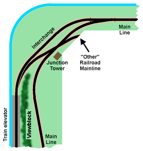
Don’t have room? Maybe your planned layout is full of “tight” features that take ALL the space. But I wonder if a “junction” needs much room. Maybe it does if it is an entire working piece of a foreign railroad. Here is the “impression” of a junction I laid out as a suggestion for a member posting here who was designing a central Texas rural layout. But this could easily be adopted to an urban setting. It uses one diamond crossing (of which only one route is actually used- no wiring problems) and one dummy (non-operating) track switch.
The “cost” in space usage of adding the junction into a track plan is the equivalent of one section of straight sectional track in the the middle of a 90 degree corner curve, and the equivalent of the width of two tracks along one back wall…one width for the track inself and one for the viewblock.
Of course, in an urban setting
Of course, in an urban setting, your viewblock would be structures, rather than the treeline suggested here.
Another scheme that allows the simulation of a junction with little space “cost.” Again, I drew this for a rural layout so ignore the “small town” caption at the bottom. This is a one-and-a-half times around-the-room point-to-point schematic where the main route crosses itself, suggesting a junction. A connecting track long enough to hold a transfer cut runs between the two tracks of the point-to-point route. In this case, you get several (but not all) of the visual elements of a real junction. It has the diamond crossing, trains operating on both ro
Opposite to usual that’s a lot of space for very little track. Your layout of course.
You might like a couple of ideas to put into the pot…
For a start you don’t need to sepearte off your “interchange tracks” at top right - just designate a couple of roads for the purpose. Personally I would make them roads at the front of the facility - if I am coupling/uncoupling locos and/or cars as a representation of interchange activity I will always find it easier to do on the tracks nearest me - saves leaning over trains on other tracks as well.
With a single track lead into a store yard I would always look to make the first switch a 3 way. This starts the most splitting the earliest possible. I want to get my switches done as soon as possible and get into plain track for the longest storage possible. In most “main track” storage length of roads is usually far more important than number of roads.
In storage the extreme front and back roads are good for kicking off a fan of a few short stubs back into the otherwise dead ground either side of the original fan of switches. These can be used for locos (a DCC encoding road can be put here) and or anything that it short and only run occasionally - like a Sperry track examiner car.
Something else I would look at (appreciating that your schematic is just that)… I would make the scenic part curved. A long shall curve is visually better than a straight. Obvi
Nothing says that your on scene track has to be flat…
It is useful to keep all tracks that detached cars will stand on level though.
So - just to play with the idea of a couple of main tracks doing something simple through the middle and level/flat… we can put a nice long curve into those tracks - with the middle away from us for a first option. This will put the store yards for these tracks at front left and front right.
Onto this we can impose a single track spur that comes from back left to back right crossing the main tracks twice.
You don’t appear to have enough length for the spur to cross the mains at different elevations so we are looking at it crossing either over, at grade or under. Given the position of the yards I would cross the spur over the main tracks. This will put the spur’s yards at least 3" higher than the main yards at the back of each yard area. This makes it easier to reach over to do any coupling/uncoupling etc.
You now have a higher line across the front of the scenic mid element… If your trains are only running through that area and you are doing little switching there this should be no problem. It gives you a different perspective on what is going on. Most of us tend to set our layouts at a height which results on us looking down on the trains anyway… it is just a matter of how the tracks are spaced front to back.
You can of course put various bridges, trestles or viaducts into the spur in addition to the bridges over the maintracks. Seen through these structures the main tracks will look distinctly different - hopefully more interesting.
If you connect short stubs to the main tracks I would do this where the main tracks are at the front of the layout… it makes life so much easier.
Option two is naturally to set the curves the other way…
What I have learnt to not do is have a low track at the far back of the stor
Once again, thanks to all. But, I see there are a few questions I need to answer. The time is 1950. Location New England coastal.
My schematic it totally simplified. East and west staging are linked. Thus I have one staging yard. The visible portion wraps around the room fully on two sides and partly on the third shelf style. The rest of the shelf style is staging. The mainline is wraps around the walls. There is a center peninsula that is an industrial area. The mainline could include passenger service and a small city station in one corner. There is a small yard on one side inside the mainline. On the side opposite from that is another more compact industrial area representing an older section of town. It is at the south end of this area that the interchange track could be located.
On my previous layout, I used a three way turnout into staging at each end of a short, 8’, shelf layout. I may do that again. Some how I’d forgotten about that. By the way, the pair of three ways worked great with the Tam Valley Frog Juicer. One juicer for 6 frogs–two three ways, 6 frogs.
I’m totally impressed by all the information I’ve been given.
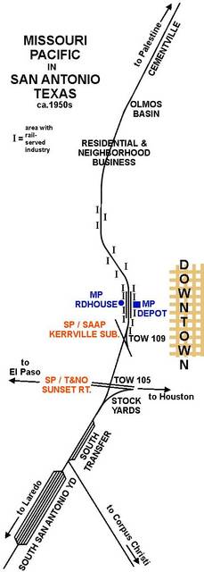
Here is an example of a prototype junction in an urban setting, and a layout element based on it.
This is the Missouri Pacific in the 1950s in . (shown in a long thread last summer)
A secondary SP line. the branch, crossed the MoP just south of the IGN/MoP depot.
There was a connection where an SP crew could drop cars in the small MoP yard next to the station.
SP’s transcontinental Sunset line crossed the MoPac near the stockyards, with a connection where an SP transfer could run to South Transfer yard. I did not plot SP lines on this map except for the crossings, but an MP transfer could ta
I am building a layout based (loosely) on the in in about 1957. is an island seaport on the . In the 1950s, two railroads- the and the , and converged at and entered the island over a 2-mile-long causeway. The , and was jointly owned by Missouri Pacific and Missouri-Kansas-Texas (MKT), and also carried the Southern Pacific tracks which joined it a few miles inland. granted trackage rights from to Burlington Lines and to .