Hi all, electronics is not my best capability and I usually spend hours looking for an easy to understand wiring diagram. So before i do that I thought one of the electronics experts here may be able to help.
I‘m looking for a complete circuit wiring diagram showing the three way turnout, Bus connections, Switch machine connections, Panel LED and toggle switch connections to the tortoises. I know how to wire teh toggle with cross wires between the end terminals.
Yes and no, There is a way to use ONE toggle with the Center OFF wired so that the 3 way is set to run trains down the center track. But of course, I don’t know how.
You need a four-pole three position rotary switch. Then make a diagram of the two Tortoises and their relation to the points.
The first Tortoise will select Diverging route or straight (Reverse or normal in RR speak)
If it is set for reverse (diverging, or route A) the second set of points don’t even come into play. If it is set for Normal then the second set of points determines what happens next, either route B or C.
With that in mind you determine which Tortoise gets a Plus or Minus DC current on terminals 1 and 8.
Sorry I can’t provide a diagram. Hopefully some of the following is partially helpful.
I have a Walthers-Shinohara code 83 3-way. As you can see in the photos of the turnout and my panel, it is a series of 2 switches, the first a left hand, the second a right hand. I simply added a Tortoise at each spot. Basically, they are independent turnouts.
I wired each switch normally, with a panel DPDT to the Tortoise, and included a bi-color (2-leg, not 3) LED in one of the wires to the Tortoise. The polarity has to be correct to get the DPDT handle position and the LED indication consistent with what you want.
I used one set of the Tortoise aux contacts to power the frog for the related switch. (The other set of aux contacts can be used to power an on-layout indicator if desired, which I did not do for the 3-way).
I wired the main rails with each bus wire as usual. The W-S turnout jumpers take care of the rest of the various rails (except for the isolated frogs). (I did not wire the moveable point rails with added jumpers as some do, relying mainly on the Tortoise pressure to hold the closed point rail in contact with the stock rail.)
I am including the Tortoise links that work. The LED application note is for dual LEDs. I preferred the single bi-color type, which is just wired in series with one of the power leads to the Tortoise.
If you wonder, the arrow pointing to one piece of rail in the photo indicates a small piece or rail that often, on the W-S 3-ways, that can allow a wheel to contact the wrong polarity and short. A bit of clear nail polish insulates to solve the problem.
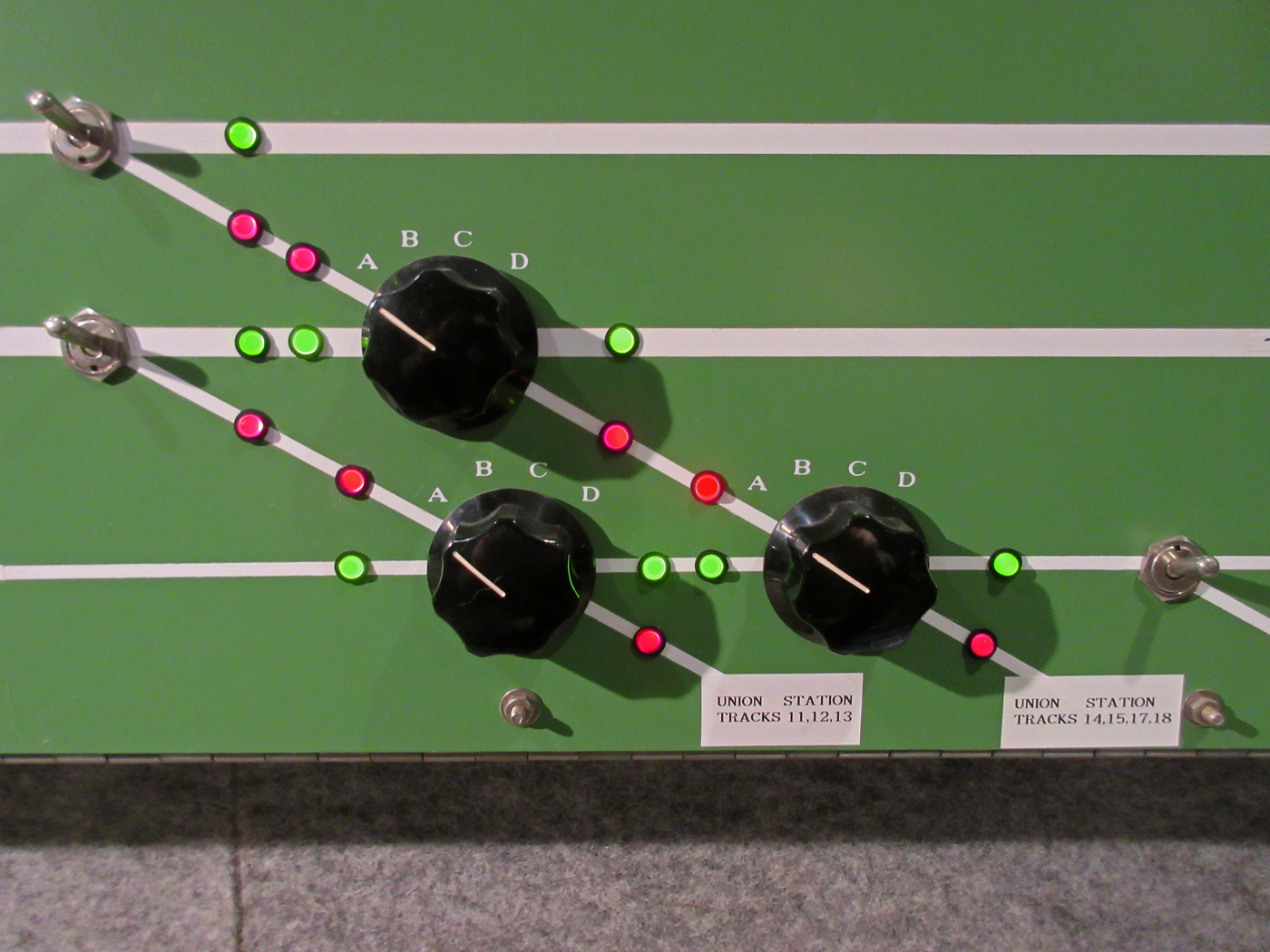
Railroaders call double-slip switches “puzzle switches”. I used rotary switches for these, along with the LEDs and it is easy to set the route through this junction:
Once you grasp the concept of how each set of points, thus each turnout motor, weather twin-coil or stall motor, has to be set it becomes clear.
It always starts out with a sketch, then a “matrix” showing the normal or reverse position of the points.
Once you have your matrix you can see how the rotary has to be wired.
In the case of the double slip there are two Tortoises. They need to have four combinations:
N — N
R — N
R — R
N — R
If you break down a four-pole rotary switch you can see where one contact on each one is a “wiper”. That will be the output wire pairs to each terminal, 1 and 8 on the Tortoise.
Then the individual points around the switch will either get the DC + or the DC — in order to make the Tortoise move in the corresponding direction.
A three way turnout is similar but the fourth position is obviously not needed.
Many rotary switches have a stop that you can set in order to reduce the number of positions used.