Hey, Gang, I’m still picking up details for my O scale 2-stall enginehouse with machine shop wing. I’ve had the furniture for the foreman’s office, plus bench vises and hand tools for the workbenches for a while and recently picked up some long-spout oilcans and larger oil cans for filling reservoirs. I have kits for a belt driven lathe, drill press, and milling machine, which will be driven by an overhead line shaft belt system via a big electric motor. Power will be provided by a boiler room annex for necessary steam and for generating power for the house, so you can see why lube oil is needed throughout.
It suddenly occurred to me that other than the tanks mounted up by the handrails on the Ma & Pa light Consols, I have no idea where the lubricating oil was stored for cylinder lubrication. I can picture enginehouse workers lugging the bigger oilcans up to top them off, but where? I’ve been studying turn of the century (20th) steam locos since Mel Thornburgh’s Wabash Mogul series in MR’s 25th Anniversary year, but the location of the lube oil reservoirs has eluded me–or at least, I can’t remember seeing them… Can anyone help me out?
Deano
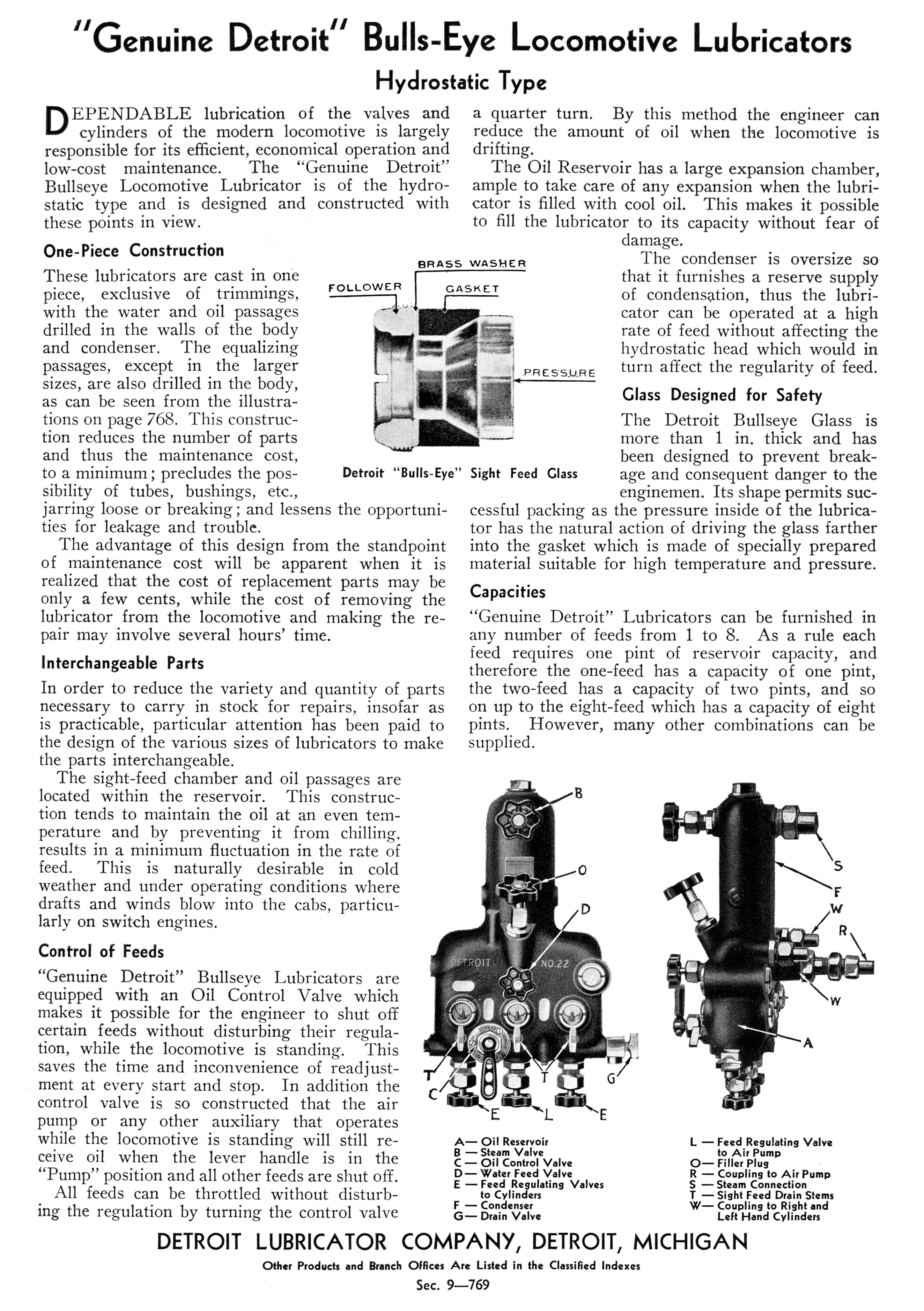
Great news, everybody: I decided to do a Google Search for “steam locomotive cab lubricators” and as usual, felt like I’d entered a maze. Surprisingly, Wikipedia finally provided the answer–in an article about British lubricators! The item names common “Wakefield and Detroit displacement lubricators” which incorporated oil reservoirs. So I Googled “o scale steam locomotive cab lubricator” and Wiseman’s LocoPainter came up. They offer the former Back Shop “DETROIT ‘BULLSEYE’ LUBRICATOR IN CAB TYPE,” which looks a lot like the ones Thronburgh put in his B&O Ten-wheeler, E27 Consol, and Wabash Mogul–except his cab items usually had square corners. The Wikipedia article said they were
Generally, you’ll see a mechanical force-feed lubricator under the walkway on the fireman’s side, sometimes on the engineer’s side, (and some larger locomotives had two) just above the valve guide. Look for an arm connecting the radius bar or the combination lever to a link on the lubricator. The lubricator has a ratchet so each movement of the valve motion causes a partial rotation of the camshaft on the lubricator.
There was a hydrostatic lubricator in the cab to lubricate the cylinders and the steam side of the air pumps and stoker engine. The air side of the compressor had their own lubricator. The stoker motor had additional lubricators for the gear racks, depending on manufacturer. Lots of places to oil on a steam locomotive.
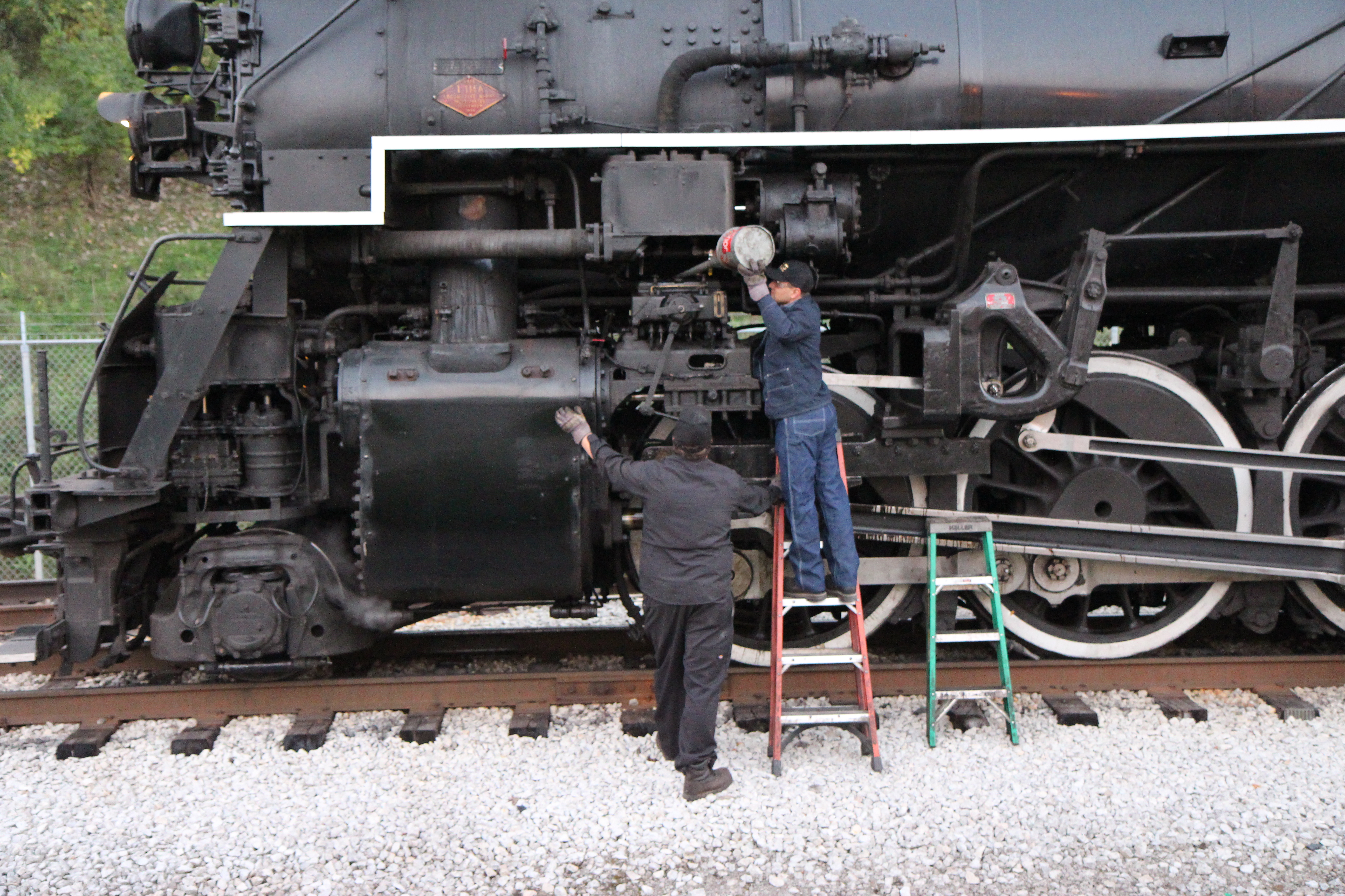
Here’s the 765 lube gang filling the mechanical lubricator:
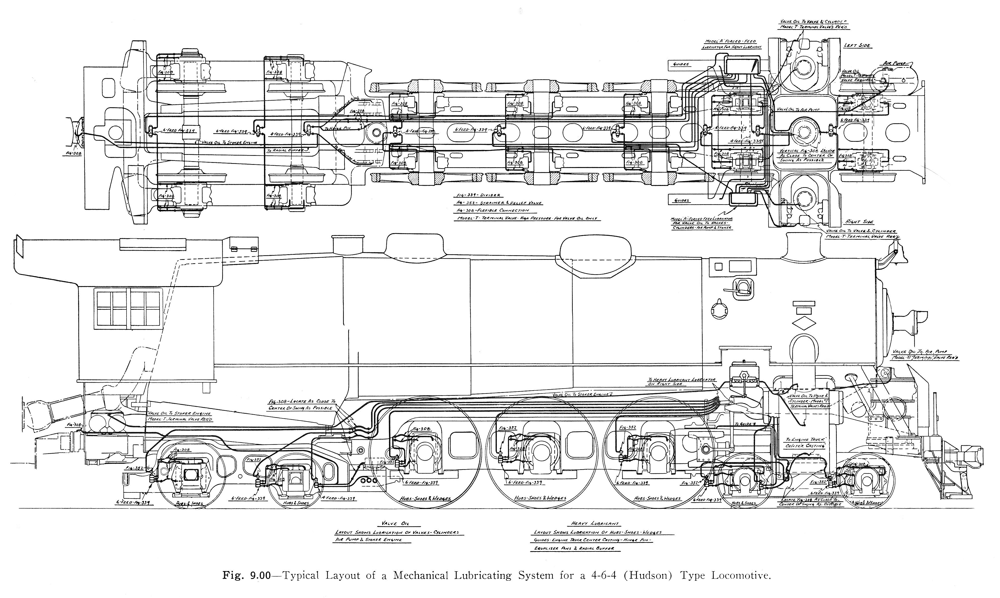
The Nickel Plate Berkshire has a mechanical lubricator on both sides. Modern locomotives had force feed lubricators for both grease and cylinder oil to places like driving box liners, hubs and pedestals.
Gidday Deano, further to Ed’s information, at 7.03, you’ll see the “Detroit Hydrostatic lubricator” situated on the back head of this NZR Ja Class locomotive being topped up, and the feed rate being adjusted.
I was under the impression that the hydrostatic lubricators were originally meant to lubricate just the pistons and valves with ‘steam oil’. Otherwise, oiling was done with cotton waste impregnated dispensers, cups, and by direct application during stops done by hand and oil can.
I found the diagrammes provided to be very useful (thanks, Ed!). I was under the misapprehension that mechanical lubrictors were for the crossheads, truck main bearings, centering springs, and equalizers. It seems they had atomizers for the cylinders and valves as well.
Your impression would appear to be correct, Crandell.
From “Locomotive Lubrication” by W.J. Schlacks, published 1911.
“Methods of Lubrication-Sight Feed, Hydrostatic. The second step in valve and cylinder lubrication taken about twenty-five years ago, was the introduction of the hydrostatic sight feed lubricator.”
Thanks, guys, but you’re talkin’ about some mighty modern stuff there, interesting though it is. I’m thinking more of the 1890-1904 era teakettles for my Mineral Point & Northern. Only one of my locos so far has piston valves; the rest have slide valves–and even the “Heavy” Consol’s piston valves are driven by Stephenson valve gear! I haven’t dug out my copies of the Thornburgh Wabash Mogul series to hunt through everything, but I remember the engineer had one of those lubricator sight boxes somewhere on his side of the firebox. I don’t recall seeing a tank anywhere in that maze, other than air tanks. I’m curious of where they kept the oil supply on the likes of those old Moguls, Ten-wheelers, Consols, and such that were the mainstays of shortlines all over the US. Just curious, mind you, but other than the Ma & Pa light Consols, with their little oil tanks up by the boiler handrails, I have no idea where it came from to go down through the tubing to the valve chests.
If you study the steam chest of the typical slide valve locomotive you’ll see a small line entering the top of the slide valve box. This is the lubricator line from the cab, generally run under the jacket and lagging.
With the advent of the superheater, the higher temperatures and dry steam required better lubricants and more of them, thus the mechanical lubricator was developed and refined, which is what I first thought you were asking about since you mentioned “reservoir”.
Sometimes folks standing too close to the engine when the cylinder cocks are open get a surprise when they see their clean, white shirts peppered with oily black spots from the atomized oil still in the exhaust steam.
The Elesco feedwater heater system (maybe others?) required an oil separator in the tender to siphon off the oil found in the exhaust steam once used to heat the water, then returned to the tender as condensate.
Gidday Deano, I’m not sure that there actually were tanks as such, though how one defines a tank by size / capacity, is open to interpretation.
Referring back to the 1911 published “Locomotive Lubrication”. “Methods of Lubrication —Hand Oiling —Oil Cups. At the outset the moisture of low pressure steam was depended upon to lubricate valves and cylinders, but soon oil cups were placed on steam chests, and were filled whenever stops were made. The next step was to place the oil cup in the cab of the loco motive, so that it could be operated by the enginemen. This method. of lubrication was nothing more than hand oiling, but it was more convenient.”
I searched Shorpy for contemporary photos and have came up with the following.
OT Dean
I don’t recall seeing a tank anywhere in that maze, other than air tanks. I’m curious of where they kept the oil supply on the likes of those old Moguls, Ten-wheelers, Consols, and such that were the mainstays of shortlines all over the US
Gidday Deano, I’m not sure that there actually were tanks as such, though how one defines a tank by size / capacity, is open to interpretation.
Referring back to the 1911 published “Locomotive Lubrication”. “Methods of Lubrication —Hand Oiling —Oil Cups. At the outset the moisture of low pressure steam was depended upon to lubricate valves and cylinders, but soon oil cups were placed on steam chests, and were filled whenever stops were made. The next step was to place the oil cup in the cab of the loco motive, so that it could be operated by the enginemen. This method. of lubrication was nothing more than hand oiling, but it was more convenient.”
Here’s a photo of a sight glass lubricator found on many turn of the century steam locomotives, in this case an NZR K class 2-4-2, built originally by Rogers Locomotive Works, New Jersey, in 1877.
You really want to see something, in one of the progress videos of the rebuild of 4014, there is a shot of one of the engnes after they ran all the lubricator lines. Talk about a mass of tubes going all over the place…
Yeah, I remember the wealthy author who did a series in Model Railroader on super-detailing steam locos in the '60s running all sorts of very fine wire “pipes” all over his HO Big Boy. I don’t remember his name but I think an O-scaler named Spanknoble had a photo spread of his O scale Big Boy somewhere back then. What a monster–about three feet long! Glad I’m modeling the days of simpler motive power.
While on the subject, some of the early road-testing videos of 4014 in the last couple of weeks show some enlightening views of what actually replaced hydrostatic lubricators, waste-filled cups, tallow etc. on modern steam.
Pressure charging of hard grease into spring-loaded reservoirs is the most common solution for non-roller side rods – the common trade name associated with this being ‘Alemite’ and you can learn a great deal about some parts of the arrangement in the Cycs. Repeated recourse to this with the initially clanking rods, sometimes multiple shots within a few minutes. In one clip you clearly see someone work the mechanical lubricator arm a few shots before starting, which was common practice – this replacing most of the old ‘oiling around’ increasingly between the 1920s and latter 1930s. Eventually as noted the little lube lines ran nearly everywhere, and were apparently often replaced or patched in somewhat cavalier fashion (the Big Boy at Steamtown a striking poster child in this respect!). At the end nearly everything including the Franklin wedges had power lube feed, each ‘channel’ being metered to give the most economical amount that got the job done.
Remember that cylinder oil is a very different thing from the other lube on a locomotive and required special arrangements to dispense.
Yes indeedy, and you can get some idea of what the stuff is like from the ‘deposits’. It is volatilized by the steam to do its job … and with the significant mass flow of the initial blow came a proportionate amount of the oil metered in, much of which ‘plated out’ on the relatively cool surfaces of the running gear, in a pattern that early on indicated where the leak was and what its likely cause could be. (By the time that picture was taken this was less clear!)
Looks with the slack like the right sprocket actually moves with the expansion link -presumably a form of proportional drive that extends the stroke of the pump the further the gear is set away from mid. Be interesting to see how that exposed Morse chain holds up in service…
From what I read somewhere eons ago. way back in time, before Valves were lubricated from a lubricator thru small-diameter tubing. When needing lubricant, slide valves would bind and drag sliding over their ports, chattering Reverse Lever and rattling linkage betwixt eccentrics and their stirrups on axle and to valves.
The Fireman or Tallow Pot would walk up along running board, he carrying a pot with a spout, containing hot lubricant to the top of the valve chest upon which was mounted a small funnel-like cup and cover with a turn key valve below which emptied into the top of the valve chest above the slide valve moving back and forth just below.
He would remove cover from funnel above turn key valve, pour in some lubricant and signal Engineer to shut off steam. The Fireman would open turn key and motion of piston would SUCK lubricant down past valve and into cylinder.
More than one shot of lubricant might be needed.
If Engineer was mad at the Fireman, he would open and shut throttle, spraying hot lubricant out over Fireman.
( Not enough STEAM !! )
See story below.
The Fireman would then shut key valve and replace cover, which would keep dirt etc out against Vacuum present when Drifting.
He then would cross over pilot and treat the other side the same way.
This procedure was done as often as was required on a trip.
As steam pressures increased, and, later, with Superheating, more satisfactory lubricants were required.</

