I’m sure the model will look great after you reassemble it.
I have vague recollections of an MR Clinic on the topic of removing a broken drill bit from zinc alloy castings, and Gordon Odegard suggesting the use of an acid or chemical that would eat away at the zinc alloy enough to allow the bit to be pulled out. How that would be controlled I do not know. Using acids that powerful in a home environment would scare me.
I agree that drilling into a drill bit is not a happy solution. If the end of the bit is at the surface, is it possible to mill in a slot so that a screwdriver could back it out? Yeah the casting gets milled too but there are putty products to fill that.
A random internet search showed that many non model railroaders also lament this problem. One guy claimed success from a tool intended to extract broken taps.
http://www.sears.com/omegadrill-t-o-broken-tap-extractors-set/p-SPM6375890705
Dave Nelson
Looking at it, if i cut off the headlight stub, there MIGHT be enough to grab with vice grips. If not i am not sure what i am going to do about part of the bit that goes through the smoke stack where the screw holds the frount on. Which ever way i go will have to wait till tommrow, as dont have time today. Thanks all for the help.
We had a tool in the miltary to remove stuck screws etc, but it is way to big for something the size i have.
The only way I have ever been able to extract a broken drill, in anything, is to get a solid grip on it with a pair of vice grips, then rotate. I think someone else mentioned that.
I learned the hard way not to try half azzed methods first. It just buggers things up and makes it even more difficult when the vice grips finally get deployed.
Best of luck with it.
CG
Used Mantua boilers pop up regularly on Ebay. If your rescue operation fails, it would be easy to replace. Working on old steamers is not always cheap, unfortunately…
It would seem to me that the broken bit in the stack area is of more concern than that for the headlight. If the broken headlight bit isn’t in the way, you should be able to use a suitable drift the bash the broken bit out in the direction from which it came. It’s unlike that you’ll find a suitable drift (at least at a reasonable price), but a suitably-sized nail might do the trick.
A hardened nail intended for use in concrete will likely work best, but any nail close in diameter to that of the hole should work. Saw or grind-off the nail’s point, then, with the boiler casting well supported (in a vise or atop wooden blocks), insert the nail, noting how deep it goes and give 'er a whack. If the depth to which the nail penetrates has increased, it’s likely that the bit has been moved. Continue whacking as necessary, checking periodically to ensure that the nail isn’t bending. If it is, prepare and use another one…otherwise, with your luck, the nail itself could become stuck. [:P]
Wayne
LOL had to google what a drift was, a punch is what i would call it, diffrent name same thing. The nail idead might work also. I plan on taking it to my dads tonight and see if there is enough showing once we cut the headlight off to grab it with vice grips.
All this now depends on time to do it, my car started engine started making bad sounds on the way home today, hope to find a place that can take a look at it for cheap, and hope nothing to $$$$ to fix. What a week, the broke bit, the paint spilled all over table floor etc, now the car and the docters visit yesterday for a thumb problem.
fourt:
Hang in there dude! Things can only get better, well at least they can get better after you see the bill for the car.[swg][|(]
I drove clunkers for many years before I could afford a decent car. I had no choice so I made the best of it. The problem these days is that rebuilding an engine is no longer a simple process.
I wish you all the best!
Dave
I cut off the headlight nub and there was about 1/4" of the bit sticking out, grabbed a channel lock pliers and gave it a tug out, it came out with no problem, why it broke i have no idea now as i figured it had got jammed in the hole. Now just have to drill the rest of the hole through the body.
The car dealership wanted 120$ just to look at it. Going to shop around monday hopefully get a better price.
fourt,
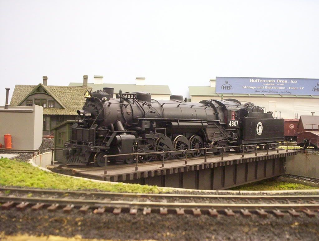
Glad you picked up the Mantua Mike. I have seen enough that were detailed and weathered to the point you could not believe the relatively crude model was the source. That is a very early model with the LARGE motor, gearbox, and brass wheels. They are supose to be good runners in stock form due to the large motor and gearing. Have fun and show us some pics of the progress.
I have a cheaper version that I was thinking of geting close to a NYC H-7, but moved to N for space reasons and a post 2008 time frame.
Just out of curiosity, have you ever disassembled a locomotive before?
I’d guess that he has, as apparently that’s where he stores his drill bits. [:P][(-D]
Wayne
one old school trick on drilling pot metal is to wax the bit , by wax i mean the white stuff cheep candles are made of.as far as the car making noise it could be a number of things ps punp going out , water pump and of the more serious side a sucked valve , broken piston ring ect ect.one other thing i just remembered is if your not in a hurry to get bit out is to keep wetting hole with water as steel rusts pot metal don’t.
Sugami motor is in my Light Mikado… Looks very simular to your Heavy Mikado except the old open frame motor…
DCC is great with the Sugami but those open frame motors kill decoders…
All the moving parts need to be cleaned and serviced, then they run well…
Best of luck with the Mantua…
lol doctorwayne that was funney. Been able to get some detail work done on the sides So it is coming along nice. As for the car probelm it turns out the oil was low. Didnt even think to check that till my dad asked if i had checked the oil. Hope to post some pictures of the model soon.
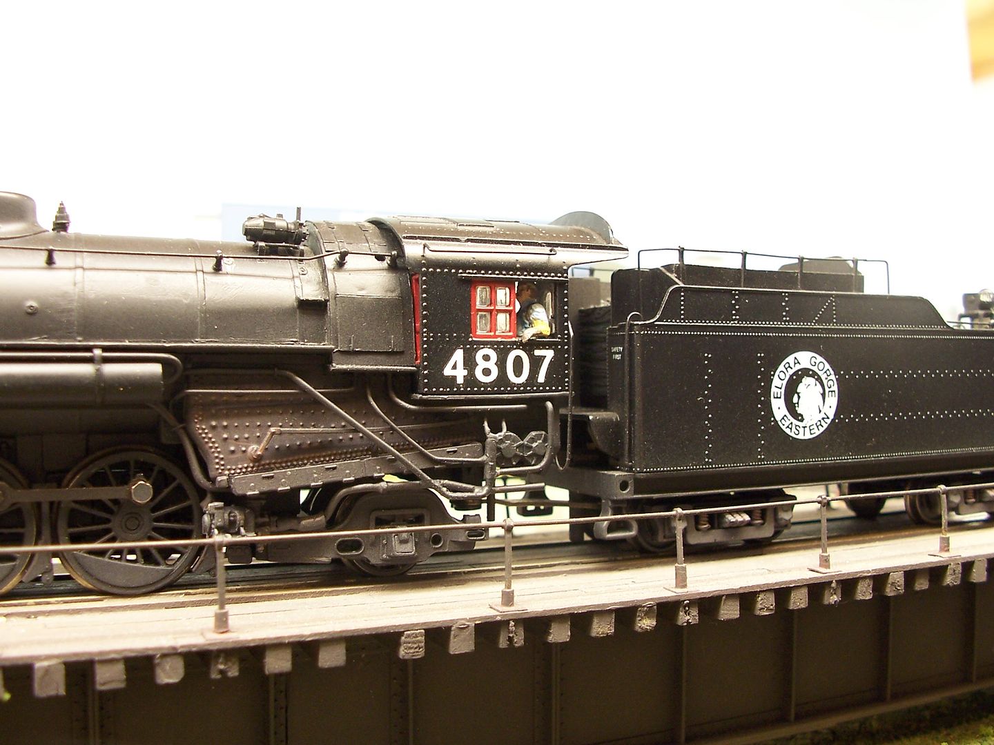
Here i what it looks like now. Hope to get some more done this weekend.


Fourt,
Looking good so far. Redetailing a steamer is great fun! Can I offer some observations though?
-
you added a check valve on the right side below the steam dome. this boiler already has a top CV just ahead of the sand dome. properly…you need to remove that and the pipes going down both sides of the boiler to the wlakways
-
you added a CC airpump to the left side at the firebox. this engine is equipped (sort of!) with 2 CC air pumps on the pilot deck. most likely they or the new one you mounted would be used but not in both locations.
3.the added sand lines on the left side would probably be matched by duplicates on the right side and not just the one new line.
-
removing the 3 sand lines already coming down from the sand dome and replacing them with the same wire used for the new lines would really help the looks there. filing them off is a PITA but the gain in looks would be a big plus.
-
it looks like you added an elesco steam ejector pump below the new CC airpump. if that’s what that is then you might want to use that file again and remove the cast on Worthington SA pump & heater on the boiler. The heater is the rectangular lump just agead of the smoke stack. the Worthington pump is the square lump below the walkway between the left cylinder and first driver. the engine wouldn’t have both types installed.
Not trying to be critical but I know you want this engine to be “right” and with all the nice work you’re doing I thought it might help you.\
Check your local library or a modeling friend and see if you can get a book called Steam Locomotive Cyclopedia Vol I by Kalmbach. It’s commonly found in public libraries and most old head modelers have a copy. It’s a great book and has drawings of many of the feedwater and other systems common to steam engines. It may provide a lot of ideas and help in this neat project.
Please keep us advised!
Roger Huber
Deer Creek Locomotive Works</
I think Roger did a great job of suggesting corrections.
Regarding 1. (quoted above): Check valves on steam locomotives are where the water is put into the boiler. For almost forever, they used TWO input “devices”. Originally, they used two injectors. Later locos often used one feedwater heater and ONE injector. Still, TWO input devices.
As the model was originally made, the two water lines met at ONE check valve location, up on top of the boiler. This was a twofer. That is, two check valves combined in one.
As the model has been modified, it has an additional check valve on the right side.
If there ever was a loco with “three” check valves, I surely don’t recall seeing one.
The problem with Roger’s suggestion is that if you remove the top check valve(s) and it’s piping, there’ll only be one check valve left. That doesn’t happen.
There are two options:
Do the removal as Roger suggests and add a left side check valve and piping.
OR.
Remove ONLY the pipe on the right side. This will leave two check valves and piping. I do believe there were single input top mounted check valves.
Well, there’s another possibilty: take off the new check valve.
Note, also, comments below about the feedwater heater and how it interacts with check valve placement and piping.
[quote]
- you added a CC airpump to the left side at the firebox. this engine is equipped (sort of!) with 2 CC air pumps on the pilot deck. most likely they or the new one yo
You may be right about that being an Elesco centrifugal pump, but the Worthington S and SA heaters did use a separate centrifugal pump for the cold water. Unless there was a difference in the capacities of the various makes, I’d guess that pump might be okay, although perhaps not a common choice.
Here’s one of the EG&E’s Mohawks, equipped with a Worthington SA feedwater heater and, right below the bottom front corner of the firebox, a centrifugal cold water pump:
Wayne
I think I was wrong in asserting that that centrifugal water pump on the model was only for an Elesco. I misread the drawings. I see that the Worthington S and SA and Coffin all used them. The Elesco sometimes did. And the Worthington BL did not.
I am not expert at telling one feedwater centrifugal pump from another. I even suspect various ones may have been used on the systems.
So I now believe the feedwater system on the left side is pretty close to right, as a Worthington S or SA. I’m referring, in particular, to the placement of the major pieces. The piping should be examined and compared to a typical piping arrangement.
That also means that the best solution for the 3-piped check valves would likely be to keep the current left side pipe arrangement, as that would be the boiler feed from the feedwater heater. And so, on the right side, one of the supplies should be removed.
Ed