Not all latching relays work that way.
More later when I have time.
Sheldon
Not all latching relays work that way.
More later when I have time.
Sheldon
as with any electronic component selection, you need to make sure the component does what you expect. It’s certrainly not a reason to dismiss considering that approach.
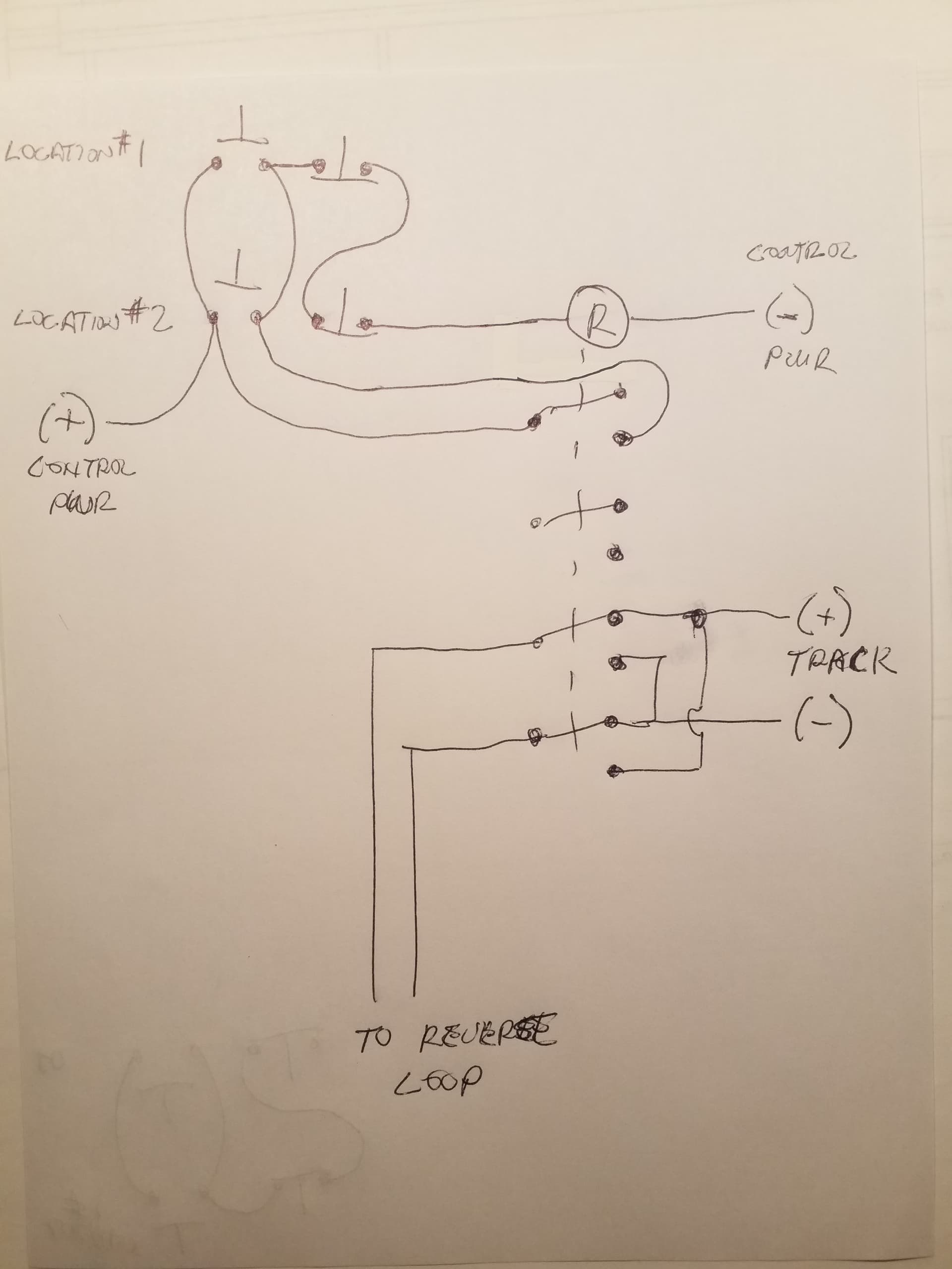
This simple circuit will give you a pushbutton station at each location. The leftover contact could change the polarity of two bi color LEDs to indicate polarity at each location.
Sheldon
i’ve honestl assessed using your approach and feel these are the trade-offs
your approach requires
latching relay approach
i feel the extra effort and cost of the switches outweighs the extra cost of the latching relay
Greg, my schematic uses pushbuttons, not dpdt switches. Shown at the top left, each of your locations would require a normally open button and a normally closed button. Those are standard symbols for pushbuttons.
Yes my schematic starts at the same default polarity on power up because the relay will default off. When the relay is off, the polarity is in one direction, when the relay is on, it is in the other. When you push either normally open button the relay is energized and seals in.
When you push either normally closed button the relay drops out and the track reverts to the opposite polarity.
You could add as many pushbutton stations to that chain as you wanted, control it from 5 locations if need be.
Sheldon
Greg, just to be clear, the flip/flop contacts below the the circle with the “R” are the relay contacts. They are shown in the de-energized state as is standard practice. The circle with the “R” is the relay coil.
Sheldon
momentary dpdt. i understand your circuitry.
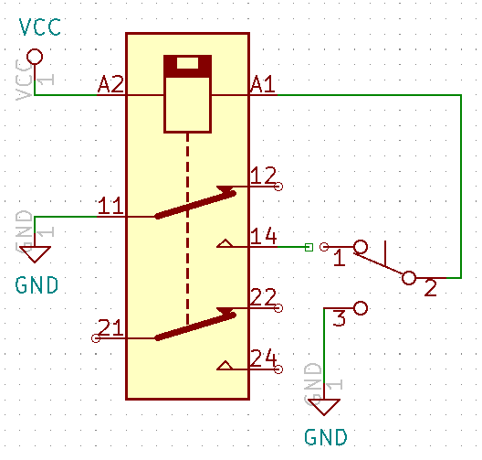
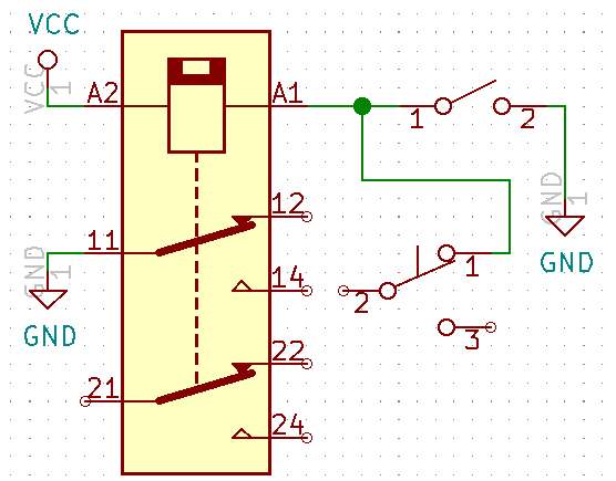
below is how you would wire it with one momentary spdt switch. but i think you need separate poles if you use multiple switches. one pole is wired in series, the other in parallel
That is why it is designed with pushbuttons rather than momentary toggle switches. The normally closed pushbuttons make the relay holding circuit work with having a latching relay.
Do you dislike pushbuttons for some reason?
ok, either momentary pushbutton or toggle switches.
but they need to be dpdt switches unless there’s a 4 terminal 2 pole switch where one pole is normally closed and the other normally open
i suggested using a spst pushbutton switch
No Greg, what you zoomed in on is one single pole normally open momentary push button and a separate single pole normally closed momentary push button.
They would be mounted side by side.
One set at each of the two locations where you desire to control the polarity. A momentary toggle is typically nornally open on both poles but even if one pole was nornally closed, yes you would need multiple poles because the normally closed holding circuit needs to be in series.
Your toggle in your circuit is double throw correct?
Separate buttons are so much simpler.
Sheldon
Pretty much since the invention of the relay and the electric motor, the two button circuit I show has been used to turn motors and other stuff on and off from multiple locations. There are reasons why separate buttons are used in favor of toggles or multi function switches.
Sheldon
confused why your drawing has 4 spst switches
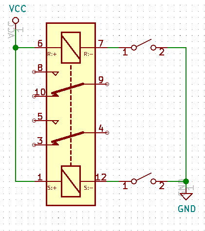
i think the following is correct. one button at each reverse section entrance. one energizes the relay. the other button releases the relay.
latching relay and 2 momentary switch
Well ok, with DCC you don’t have to consider the mainline ever changing so yes you can eliminate the ability to put it in either state from either end. But it still might be a nice option to have.
For what it’s worth, in relay systems the control circuits are typically positive or hot and the coil is grounded.
I know the solid state workd works opposite that.
Sheldon
don’t under stand. are the 2nd set of switches to control a 2nd relay for the mainline polarity.
isn’t this one controlling the reverse section polarity?
And, for what it is worth, in the relay world we ground the coil, not the control circuit. I know the solid state world is the other way around.
Sheldon
No. I am going to have to talk to you later, I am working. One relay, the ability to turn it on and off from borh ends. When it is off the reverse section polarity is one way, when it is on the polarity is the other way.
All parts and wiring shown on my drawing.
Sheldon
With DCC, you would never change the “polarity” (phase) of the mainline, so for each entrance to the reversing section, only one relay state will match the mainline so you only need one button. With DC, the relay state that matches the mainline at a particular entrance will be dependent on which direction the mainline is set for, so you’ll need two buttons at each entrance. There are at least two exceptions to this: