I am designing a HO scale walk-around layout. Most of the layout is 2 feet deep, some places a little more. I would like to model a double main line around the room with the outside line have 30" R and the inside to have 27" R or 27 1/2" R. How do I measure the curves? The focal point will be off the table so drawing a radius is a challenge.
If you have a tripod you can use it with astick. You can also make one from from scrap wood then you can move it around as needed.
That pretty much covers it. Not sure I’d bother with trying to make a tripod, as I’d probably fail on that. But anything that you can set in place that is solid enough to use as the center point of your arc will work. If you have benchwork up on both sides of an aisle, you can temporarily screw a piece of lumber from side to side that spans across the spot where the center point will be. Then mark it on the stick, scribe your arc, and remove the stick.
Draw the arc(s) on a piece of cardboard and cut out a template to draw your curves.
I did the same thing. I built a small table (2’ x 2’) the same height as the layout and ran a length of 1" x 2" pine board across to the layout. With a pencil placed through a hole in the pine board at the appropriate distance, I was able to trace the desired radius.
You could also use something like a Ribbonrail metal track alignment gauge to trace the desired radius.
Rich
I measured for my radii using the layout to support a board, which in-turn supported the trammel. That was mainly to get a rough idea of how broad of a curve would fit and still come out of the curve at a suitable point. Screw or clamp one end of the board to the layout so that its other end projects out from the corner into the aisle, and try describing various radii with an adjustable trammel ( I used a 4’ length of 3/8" plywood, with holes for both a pencil and a pivot placed on 2" centres). You can also experiment with moving the position of both the fixed and/or free ends of the support board to permit altering where the curves begin and end.
You may want to try this for the same reason that I did, too, as you should be able to get a much wider radius within that 2’ depth.
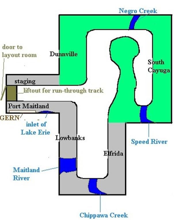
I built my layout without using a trackplan, so my first task was to find the widest curves which would fit at the 10 corners of the room (plus into- on- and out-of the peninsula). The “trackplan” was then completed by joining all of the curves with straight (or not so straight) sections.
Here’s the room with which I had to work (as you can see, there’s still no trackplan). [swg]
If you’re set on those radii, simply trace them out (separately) on some cardboard - a large flattened box from the supermarket or appliance store is a good source - then cut them out as track-width or subroadbed-width templates. I’d suggest making the cardboard arcs greater than 90°, as it will allow you the option of having the entry/exit track at the ends of the curve come back out towards the aisle. You can also have those tracks stray somewhat closer to the wall simply by ending the curve before it’s made a full 90° turn. Either way, this allows you to keep the track on the straight areas fro
Personally, I like trying all methods. It is a sure-fire way to find out what you don’t like to do, and you find a method that works for you. Sort of like laying flextrack…the best way to figure out how to do it is to do it.
I like the idea of plywood or cardboard templates made using a sabre saw/jigsaw, and just laying it along your centerline where you need a curve. Or, I have used a camera tripod and simply tape or somehow stuck a trammel (length of lath) at a defined pivot point to the mounting screw, and then moved the tripod until the trammel marks show that I have the right radius when the right mark covers the centerline. Stick a pencil into a pre-drilled hole in the trammel there, or just hold the pencil so with fingers where you know the length is right, and sweep the trammel in an arc. The camera mounting screw will allow the trammel to pivot.
Crandell
I made cardboard templates 1" wide. That way one template is good for two different radiuses. I tend to lay track without drawing every inch out on the bench. I think it looks better not having that set radius, stamped out look, and as long as I don’t go below my minimum radius, which I constantly check with my cardboard templates I am happy.

Brent[C):-)]
Don’t forget to allow for easements at each end of the arc!!!
Dave
Some form of all of these techniques were employed in Senior High in the all-afternoon Vocational Drafting Class. Many drawings from machine parts, to buildings, to topography & landscaping, to freight car, etc. required “off-the-drawing” radius measurements, and the radius also needed to be documented for course grades.
My preferred technique is to use cardstock templates, but with a twist. I draw them (on a flat worktop with a trammel) with centerline, inner tie line and outer tie line. Then I cut along the tie lines. Putting them in place tells me EXACTLY where the track will be, and whether or not my articulated will clear that immovable object (support for track at higher levels.) I sometimes bend some flex atop the template and physically test my bulkier rolling stock for clearance - a guarantee that there won’t be any [oops] moments in my future.
Another alternative, which I hesitate to suggest, involves using the same methods our prototype brethren use, with a 100 (scale) foot measuring stick and a protractor. A little trigonometry will give you the offset angle per 100 foot chord. You could be the only model rail in town who actually measures his curves in degrees…[:-^]
Chuck (Modeling Central Japan in September, 1964 - where the prototype stated radius in meters)
With access to a computer and a simple drawing program (doesn’t have to be a model rr program), you can draw the radii on the computer and print them out at full scale, i.e., 1 to 1. Apply print-outs to layout and transfer by punching holes in the paper along the lines of the curves with anything handy.
Dante