Hey Guys. I have a number of Miller Engineering signs and billboards on my layout, as many of you may. Have several more I’m contemplating placing, but… they’re so SHINY! I’d like to dull the surface finish so tney don’t stick out so much, maybe with one or two coats of Dullcote? Has anybody else tried this, does it work, and does it adversely affect the functions of the sign?? If not Dullcote, any other suggestions to kind of “blend in” the signs so they’re not so glaringly different from the weathered buildings?
My Miller Engineering signs aren’t shiny. They’re pretty old but I don’t remember them being shiny when I first installed them. Then again when they are on and doing their thing the shine shouldn’t be noticeable.
Might drop them a line and ask about Dullcote.
Mel

My Model Railroad
http://melvineperry.blogspot.com/
Bakersfield, California
I’m beginning to realize that aging is not for wimps.
I don’t own any Miller Engineering Signs, so I don’t know for sure, but can you install a resistor to reduce the current passing through the sign? On the website, it says that all animated signs draw 95 ma.
Rich
The Miller signs are Electroluminescence and have a high voltage power supply, the Electroluminescence (EL) requires about 90 volts to operate. Putting a resistor in series might ding the power supply.
Mel
My Model Railroad
http://melvineperry.blogspot.com/
Bakersfield, California
I’m beginning to realize that aging is not for wimps.
I don;t have anym, but I don’t recallt he ones on the club layout being shiny when not lit. I don’t think the material the EL wire is made of will be hurt by Dulcote, but I would test before ruinign a sign. A water-based dulling spray would be better than a solvent based one, less likely to cause any damage to the amterials of the sign.
It would make the sign thicker, so depending on the use, it may or may not matter, but a thin piece of clear styrene, lightly sanded to frost it, overlayed would make the whole think a lot less shiny.
–Randy
LOL. Thanks, Mel. I wondered if I might regret raising that issue. Glad I began that post with "I don’t know sure, but…
Just curious, how are these signs powered? The website mentions 3 AAA batteries.
Rich
On the Miller website they say the signs are 4.5 volts.
Is this a change? Were the older signs 90 volts?

-Kevin
Electroluminescence (EL) requires high voltage to operate, the Miller signs come with a power supply that converts the 4.5 volts to high voltage. EL lighting element runs on 90+ volts.
https://hackaday.com/2011/08/25/all-about-electroluminescence/
Mel
My Model Railroad
http://melvineperry.blogspot.com/
Bakersfield, California
I’m beginning to realize that aging is not for wimps.
The power supply is 4.5 volts. But that runs a little circuit that is a boost converter. The signs are made with an electroluminescent sheet or wire, depending on the form of the sign, and those things run on high voltage (but low current).
Thicker versions of the EL wire were often used by people to decorate their computer cases before RGB LEDs became so common (and I still laugh every time they come up with somethign new to add RGB lighting to, always sold as “gamer” - yeah, that stuff is the gamer equivalent to the cut spring Hondas with fart can mufflers pretenting they are now “performance” cars. A serious gamer would save the money on that garbage and spend it on the next level up video card).
Back when I was a kid, I had some of those Radio Shack Science Fair kits - they originally had a red plastic perforated base, with a clear cover, all the parts and instructions were packed inside. One I had used a row of neon bulbs that would light in sequence, or at random depending on which of two wiring options you did, power source was I think a (V batter, but neon bulbs need 80-100 volts, so the main part of the circuit was a step up converter. You could get a tingle if you touched the wrong part, but it was very low current and not aprticularly dangerous. I know mine had a cheap transformer, it had very audible coil whine when running.
If you look on the Miller site under the Experimenter’s Kits section, you cna see the little power supply that goes between the battery and the EL panel (or between the AC adapter and the EL panel). A clearer view is item #2701 - Inverter. The item on the left, you can see the transformer and two large capacitors (there are more components also) - that’s the step up voltage converter to generate the 90V or so required by the EL sheets and wires.
–Randy
Thanks for clarifying that detail for me.
I was confused… even a little bit more than normal.
[:^)] [^o)] [-)] [%-)] [:^)] [^o)] [-)] [%-)]
-Kevin
If you think back about 30 or 40 years the panel night lights were EL lighting.
Mel
My Model Railroad
http://melvineperry.blogspot.com/
Bakersfield, California
I’m beginning to realize that aging is not for wimps.
So, going back to the OP’s issue, he is objecting to the fact that his signs are shiny which made me wonder if they are too bright.
Rich
I think his have a shiny surface when off. I seldom turn my Miller signs off but just for kicks I took a look at several of mine a couple of minutes ago and they don’t look shiny to me.
Mel
My Model Railroad
http://melvineperry.blogspot.com/
Bakersfield, California
I’m beginning to realize that aging is not for wimps.
In my opinion, the easiest way to deal with a sign like a Miller is just to cut a piece of lightly ‘frosted’ adhesive clear plastic sheet to get a nonglare surface. In theory you could use non-glare glass like that made for photo frames, or another framing “solution” to reduce the shine. You will only want to apply this over the actual ‘image’ as otherwise the matte may show the blank or clear part of the sign just as frosted glass would.
In order to reduce intensity of an EL panel you’ll need a constant-current power supply that lets you adjust current independent of voltage. But incidentally you don’t need fancy electronics to drive the things. Chrysler had some of the most spectacular dashboards ever created, better than pinball machines, that were implemented using what they called “Panelescent” technology (you will occasionally see this spelled very imaginatively in old-car posts, my personal favorite being “paleovescent”) and of course these needed early-Sixties, car-manufacturer-cost-effective, electrical means to drive them. You were of course supposed to think there was some space-age optoisolated solid-state module back under the dash that ran this miracle lighting – the truth was rather less grand, more interesting, and decidedly not high-tech. (Think Model T ignition, for a start… [:-^]
One of these hooked up to a nominal 12V source with appropriate voltage-dropping resistors ought to drive a Miller panel just fine, and more to the point perhaps it should be possible to re-create one with a few cheap modern parts and scraps of material.
I use the cheapo DC to DC Buck Converters for my layout, super efficient switching power supplies. You can get them from 1 amp to 12 amps for under $2 to $5 off eBay.
It would be best to use a voltage regulated source. The signs have selectable sequencing for different modes and I think the 95ma is the max on the Miller signs, the current flexes a bit with the different modes.
Mel

My Model Railroad
http://melvineperry.blogspot.com/
Bakersfield, California
I’m beginning to realize that aging is not for wimps.
EL is one of those cool early-Sixties technologies like Nimo tubes, which requires high voltage to work, admittedly very low-current but not always with effective current limiting if shorted inadvertently by human contact or even proximity [:O]
My suspicion is that you do not ‘dim’ these panels by reducing the voltage: you will get to a certain level and they’ll just go out. So you have to keep the voltage reasonably fixed and then vary the current… which requires a different circuit downstream of whatever determines or supports the voltage. Not necessarily difficult or more expensive, just a set of requirements to be accommodated.
Yea, the brightness seems fixed and doesn’t change under primary voltage, they are either on or off. The current only varies a few ma for the different modes. I have quite a few Miller signs running of a 12 volt powered Buck converter set to 4.5 volts, incidentally none of my Miller signs draw 95ma, six signs draw a total of .426ma at 4.5 volts. The Buck converters are great little devices, super compact, great voltage and current regulation and best of all no heat!
Mel
My Model Railroad
http://melvineperry.blogspot.com/
Bakersfield, California
I’m beginning to realize that aging is not for wimps.
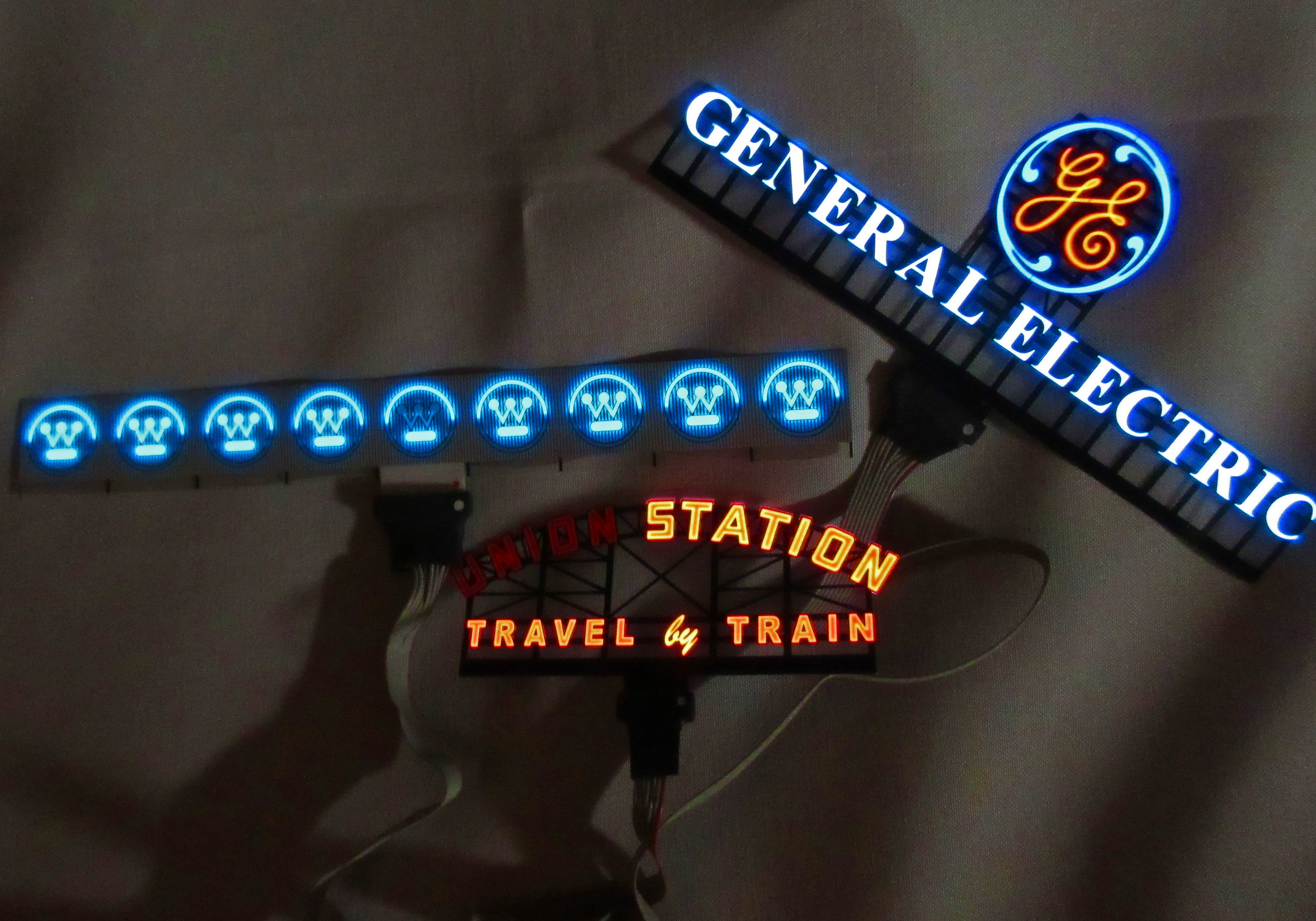
Mine are shiny on the surface but most are located “deep” enough in the scene not to be noticeable.
 Miller_zippo by Edmund, on Flickr
One thing I CAN attest to is the 90 volts of high frequency current. Don’t grab the PC board while energized. Glad I don’t have a pacemaker! [xx(]
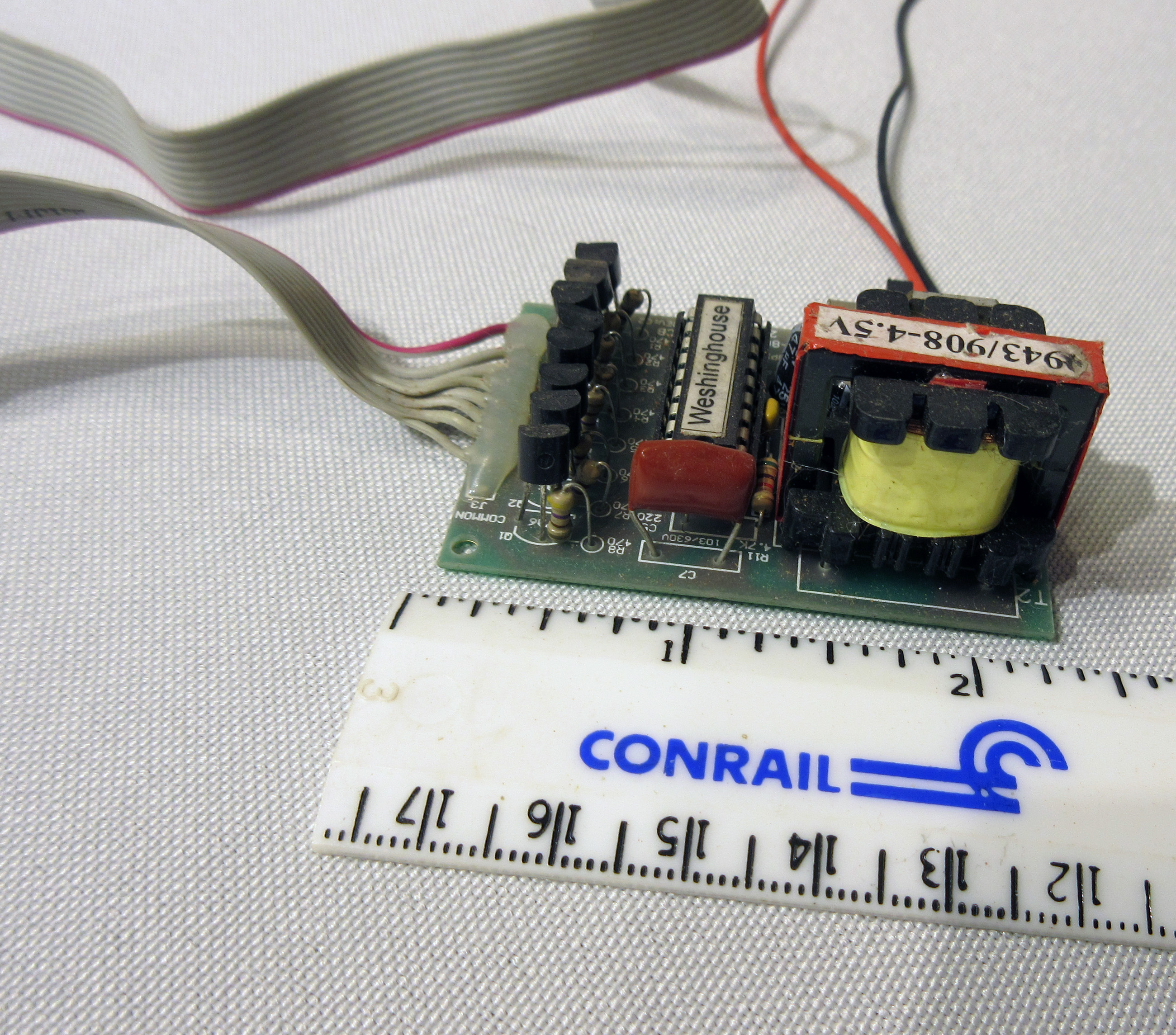 Miller_11-2-pc by Edmund, on Flickr
I bought some LED string lights that came with a 4.5V wall wart. These drive six of my signs without any trouble. I did buy the Miller 12 > 4.5 V reducer but haven’t found a need to wire it in just yet.
I have an older non-working sign that I can give a shot of DullCote to later and see how it works. It will reduce some of the sharpness of the image, of course. Kind of like trying to see out a fogged window. The front of the sign seems to be plain acetate so I don’t think the DullCote will affect it.
 Miller_11-2 by Edmund, on Flickr
My Union Station sign has a bad contact on the left-hand segment [:(]
Good Luck, Ed
Hmmm … has anyone tried square-wave PWM (at 90-volt amplitude) on these things? Reducing the on-time duty cycle ought to reduce the apparent brightness and at something like 20K frequency the persistence of vision ought to keep flicker down for a considerable range …
Hey, Ed, I hear opportunity knocking! I’d bet just sticking a pin carefully into the panel would pick up that segment – then drive it off a separate supply. And rig something like one of those old commutators for waterfall or fire-flicker simulation, and hook it up so the ‘broken’ segment flickers pseudorandomly like an old neon display going bad… might be evocative of a whole certain era… [:-^]